REMOVAL
Removal / installation · Vehicles built from Aug 2007
Versions by build date: Nov 2005 – Dec 2006 Jan 2007 – Jul 2007 from Aug 2007
| 1.
DISCONNECT CABLE FROM NEGATIVE BATTERY TERMINAL |
 |
- CAUTION:
- Wait at least 90 seconds after disconnecting the cable from the negative (-) battery terminal to prevent airbag and seat belt pretensioner activation.
| 2.
REMOVE FRONT SEAT ASSEMBLY LH |
|
Remove the front seat.
for Manual Seat (Click here)
for Power Seat (Click here)
| 3.
REMOVE FRONT SEAT ASSEMBLY RH |
|
Remove the front seat.
for Manual Seat (Click here)
for Power Seat (Click here)
| 4.
REMOVE REAR NO. 1 SEAT ASSEMBLY LH |
|
Remove the rear No. 1 seat (Click here).
| 5.
REMOVE REAR NO. 1 SEAT ASSEMBLY RH |
|
Remove the rear No. 1 seat (Click here).
| 6.
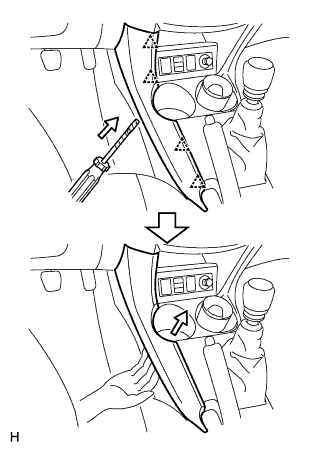
REMOVE NO. 1 CONSOLE UPPER PANEL GARNISH
|
|
Using a screwdriver, detach the 4 clips and upper panel garnish.
- HINT:
- Tape the screwdriver tip before use.
| 7.
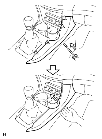
REMOVE NO. 2 CONSOLE UPPER PANEL GARNISH
|
|
Using a screwdriver, detach the 4 clips and upper panel garnish.
- HINT:
- Tape the screwdriver tip before use.
| 8.
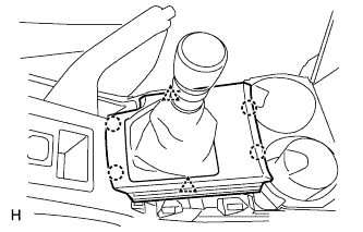
REMOVE UPPER CONSOLE PANEL SUB-ASSEMBLY
|
|
Remove the shift lever knob.
for Manual Transaxle:
Using a screwdriver, detach the 2 clips, 4 claws and remove the upper console panel.
- HINT:
- Tape the screwdriver tip before use.
for Automatic Transaxle:
Using a screwdriver, detach the 2 clips, 4 claws and remove the upper console panel then disconnect the connector.
- HINT:
- Tape the screwdriver tip before use.
| 9.
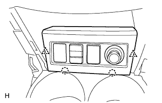
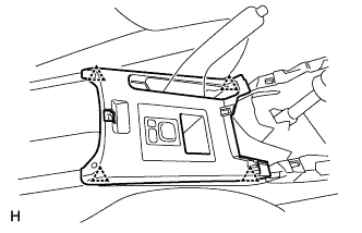
REMOVE SWITCH BASE
|
|
Detach the 2 clips and 2 claws.
Disconnect the connectors and remove the switch base.
| 10.
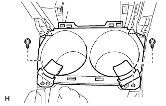
REMOVE CONSOLE CUP HOLDER BOX
|
|
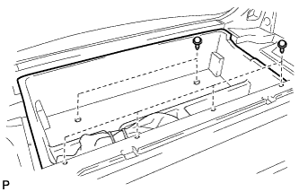
Remove the 2 screws.
Detach the 2 clips and remove the cup holder box.
| 11.
REMOVE UPPER REAR CONSOLE PANEL SUB-ASSEMBLY
|
|
Using a screwdriver, detach the 4 clips.
- HINT:
- Tape the screwdriver tip before use.
Disconnect the connector and remove the upper rear console panel.
| 12.
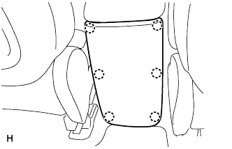
REMOVE CONSOLE REAR END PANEL
|
|
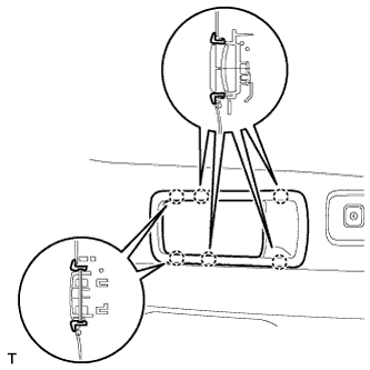
Using a screwdriver, detach the 6 claws and remove the console rear end panel.
- HINT:
- Tape the screwdriver tip before use.
| 13.
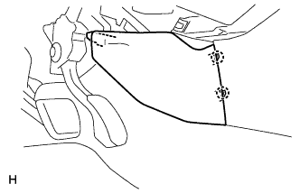
REMOVE NO. 1 INSTRUMENT PANEL BRACKET COVER INNER LH
|
|
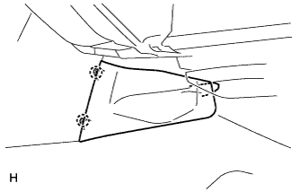
Detach the 2 claws and remove the instrument panel bracket cover.
| 14.
REMOVE NO. 1 INSTRUMENT PANEL BRACKET COVER INNER RH
|
|
Detach the 2 claws and remove the instrument panel bracket cover.
| 15.
REMOVE REAR CONSOLE BOX SUB-ASSEMBLY
|
|
Remove the console box carpet.
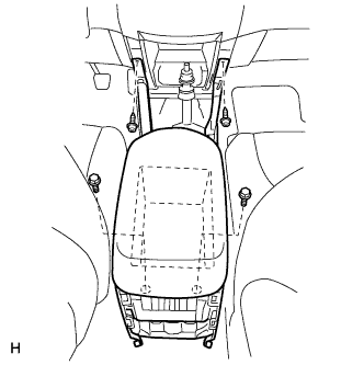
Remove the 2 bolts and 2 screws.
Disconnect the connector and remove the rear console box.
| 16.
REMOVE FRONT DOOR SCUFF PLATE LH |
|
Remove the front door scuff plate.
for Short Body (Click here)
for Long Body (Click here)
| 17.
REMOVE FRONT DOOR SCUFF PLATE RH |
|
Remove the front door scuff plate.
for Short Body (Click here)
for Long Body (Click here)
| 18.
REMOVE COWL SIDE TRIM BOARD LH |
|
Remove the cowl side trim board.
for Short Body (Click here)
for Long Body (Click here)
| 19.
REMOVE COWL SIDE TRIM BOARD RH |
|
Remove the cowl side trim board.
for Short Body (Click here)
for Long Body (Click here)
| 20.
REMOVE FRONT DOOR OPENING TRIM WEATHERSTRIP LH |
|
| 21.
REMOVE FRONT DOOR OPENING TRIM WEATHERSTRIP RH |
|
| 22.
REMOVE REAR DOOR SCUFF PLATE LH |
|
Remove the rear door scuff plate.
for Short Body (Click here)
for Long Body (Click here)
| 23.
REMOVE REAR DOOR SCUFF PLATE RH |
|
Remove the rear door scuff plate.
for Short Body (Click here)
for Long Body (Click here)
| 24.
REMOVE REAR DOOR OPENING TRIM WEATHERSTRIP LH |
|
| 25.
REMOVE REAR DOOR OPENING TRIM WEATHERSTRIP RH |
|
| 26.
REMOVE LOWER CENTER PILLAR GARNISH LH |
|
Remove the lower center pillar garnish.
for Short Body (Click here)
for Long Body (Click here)
| 27.
REMOVE LOWER CENTER PILLAR GARNISH RH |
|
Remove the lower center pillar garnish.
for Short Body (Click here)
for Long Body (Click here)
| 28.
REMOVE PACKAGE TRAY TRIM POCKET SUB-ASSEMBLY |
|
Remove the package tray trim pocket.
for Short Body (Click here)
for Long Body (Click here)
| 29.
REMOVE TONNEAU COVER ASSEMBLY |
|
Remove the tonneau cover.
for Short Body (Click here)
for Long Body (Click here)
| 30.
REMOVE REAR FLOOR NO. 1 BOARD |
|
Remove the rear floor No. 1 board.
for Short Body (Click here)
for Long Body (Click here)
| 31.
REMOVE DECK BOARD ASSEMBLY |
|
Remove the deck board.
for Short Body (Click here)
for Long Body (Click here)
| 32.
REMOVE REAR FLOOR NO. 3 BOARD |
|
Remove the rear floor No. 3 board.
for Short Body (Click here)
for Long Body (Click here)
| 33.
REMOVE REAR FLOOR NO. 2 BOARD |
|
Remove the rear floor No. 2 board.
for Short Body (Click here)
for Long Body (Click here)
| 34.
REMOVE JACK CARRIER ASSEMBLY (for Short Body)
|
|
Using a clip remover, remove the 7 clips and remove the jack carrier.
| 35.
REMOVE REAR FLOOR NO. 1 MAT SUPPORT SIDE PLATE |
|
Remove the rear floor No. 1 mat support side plate.
for Short Body (Click here)
for Long Body (Click here)
| 36.
REMOVE BACK DOOR WEATHERSTRIP |
|
| 37.
REMOVE REAR FLOOR FINISH PLATE |
|
Remove the rear floor finish plate.
for Short Body (Click here)
for Long Body (Click here)
| 38.
REMOVE RECLINING REMOTE CONTROL LEVER BEZEL LH
|
|
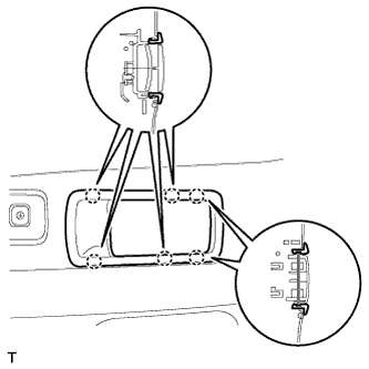
- Using a screwdriver, detach the 6 claws and remove the bezel.
- HINT:
- Tape the screwdriver tip before use.
| 39.
REMOVE RECLINING REMOTE CONTROL LEVER BEZEL RH
|
|
- Using a screwdriver, detach the 6 claws and remove the bezel.
- HINT:
- Tape the screwdriver tip before use.
| 40.
REMOVE TETHER ANCHOR BRACKET SUB-ASSEMBLY (for Long Body)
|
|
- Remove the bolt and tether anchor bracket.
| 41.
REMOVE CHILD RESTRAINT SEAT TETHER ANCHOR COVER |
|
| 42.
REMOVE CHILD RESTRAINT SEAT TETHER ANCHOR BRACKET |
|
| 43.
REMOVE DECK TRIM SIDE PANEL ASSEMBLY LH |
|
Remove the deck trim side panel.
for Short Body (Click here)
for Long Body (Click here)
| 44.
REMOVE DECK TRIM SIDE PANEL ASSEMBLY RH |
|
Remove the deck trim side panel.
for Short Body (Click here)
for Long Body (Click here)
| 45.
REMOVE FRONT FLOOR CARPET ASSEMBLY |
|
Partially remove the floor carpet.
- HINT:
- It is not necessary to fully remove the floor carpet. Partially remove it so that the lock control cable can be removed in a later step.
| 46.
REMOVE FUEL LID LOCK CONTROL CABLE SUB-ASSEMBLY |
|
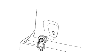
Remove the bolt and fuel lid lock open lever.
Remove the tape and cable from the clamps as shown in the illustration.
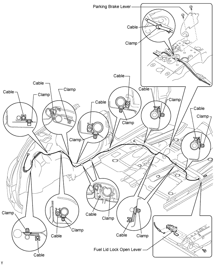

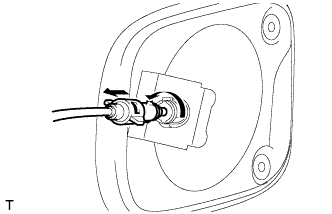
- Turn the lock retainer counterclockwise and remove the cable from the retainer.
| 47.
REMOVE FUEL FILLER OPENING LID LOCK RETAINER |
|
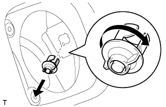
Turn the lock retainer clockwise and remove the lock retainer as shown in the illustration.