2005-2008 RAV4 · Service Manual ENGINE

REMOVAL

Removal / installation · Vehicles built Jan 2007 – Jul 2007

Versions by build date: Nov 2005 – Dec 2006 Jan 2007 – Jul 2007 from Aug 2007


1. DISCHARGE REFRIGERANT FROM REFRIGERATION SYSTEM
  1. Start up the engine.

  1. Turn the A/C switch ON.

  1. Operate the cooler compressor with an engine speed of approximately 1,000 rpm for 5 to 6 minutes to circulate the refrigerant and collect the compressor oil remaining in each component into the cooler compressor.

  1. Stop the engine.

  1. Using SST, discharge the refrigerant gas.

    SST
    07110-58060   (07117-58060, 07117-58070, 07117-58080, 07117-58090, 07117-78050, 07117-88060, 07117-88070, 07117-88080)


2. DISCONNECT CABLE FROM NEGATIVE BATTERY TERMINAL

CAUTION:
Wait at least 90 seconds after disconnecting the cable from the negative (-) battery terminal to prevent airbag and seat belt pretensioner activation.


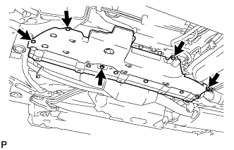
3. REMOVE NO. 1 ENGINE UNDER COVER
  1. Remove the 4 bolts, 12 clips and under cover.


4. REMOVE ENGINE UNDER COVER REAR RH
  1. Remove the 2 clips and under cover.


5. REMOVE ENGINE UNDER COVER REAR LH
  1. Remove the 2 clips and under cover.


6. REMOVE NO. 2 ENGINE UNDER COVER
  1. Remove the 2 clips and under cover.


7. REMOVE FRONT FLOOR COVER

  1. A130273
    Remove the nut, bolt, 3 clips and floor cover.


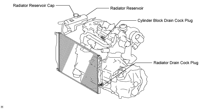
8. DRAIN ENGINE COOLANT
  1. Loosen the radiator drain cock plug.

    HINT:
    Collect the coolant in a container and dispose of it according to the regulations in your area.

  1. Remove the radiator reservoir cap.

    CAUTION:
    Do not remove the radiator reservoir cap while the engine and radiator are still hot. Pressurized, hot engine coolant and steam may be released and cause serious burns.

  1. Loosen the cylinder block drain cock plug.

    A126839E01


9. DRAIN ENGINE OIL
  1. Remove the oil filler cap.

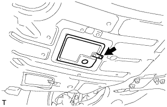
  1. A123522
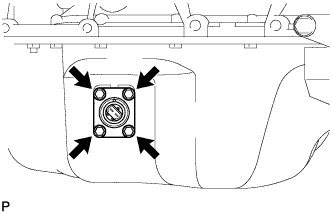
    Remove the clip and open the oil pan drain service cover.

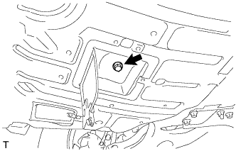
  1. A123521
    Remove the oil drain plug and gasket, and drain the engine oil into a container.


10. DRAIN MANUAL TRANSAXLE OIL
  1. Remove the filler plug and gasket.

  1. Remove the drain plug and gasket, and drain the oil.

  1. Install a new gasket and the drain plug.

    Torque:
    49 N*m{ 500 kgf*cm , 36 ft.*lbf }


11. DRAIN TRANSFER OIL
  1. Remove the drain plug and gasket, and drain the oil.

  1. Install a new gasket and the drain plug.

    Torque:
    49 N*m{ 500 kgf*cm , 36 ft.*lbf }


12. REMOVE HOOD SUB-ASSEMBLY

  1. B127320E01
    Remove the 4 bolts and hood.


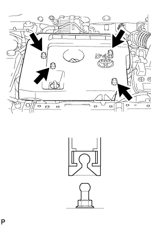
13. REMOVE NO. 1 ENGINE COVER

  1. A123518
    Detach the 4 clips and remove the engine cover.


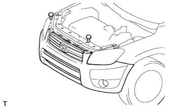
14. REMOVE RADIATOR SUPPORT OPENING COVER

  1. B130259
    Remove the 2 clips.

  1. Partially remove the radiator support opening cover.

    HINT:
    It is not necessary to fully remove the radiator support opening cover. Partially remove it so that the bumper cover can be removed later.


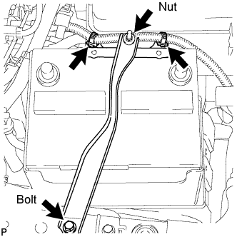
15. REMOVE BATTERY CLAMP SUB-ASSEMBLY

A124917E01
  1. Remove the bolt and loosen the nut.

  1. Detach the 2 wire harness clamps.

  1. Detach the hook of the battery clamp from the front battery bracket, and then remove the battery clamp.


16. REMOVE BATTERY

17. REMOVE FRONT BATTERY BRACKET

  1. A124918
    Detach the 2 wire harness clamps.

  1. Remove the 4 bolts and front bracket.


18. REMOVE BATTERY BRACKET REINFORCEMENT

  1. A124919
    Remove the 2 bolts and bracket reinforcement.


19. REMOVE AIR CLEANER CAP SUB-ASSEMBLY

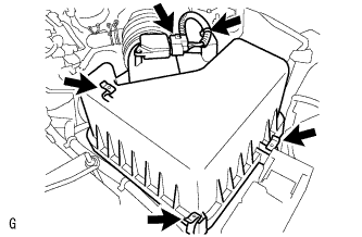
  1. A124927E01
    Disconnect the mass air flow meter connector.

  1. Disconnect the wire harness clamp.

  1. Unhook the 3 hook clamps, and then remove the air cleaner cap.

  1. Remove the air cleaner filter element from the air cleaner case.


20. REMOVE AIR CLEANER CASE

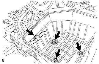
  1. A124928E01
    Disconnect the wire harness clamp and remove the 3 bolts and air cleaner case.


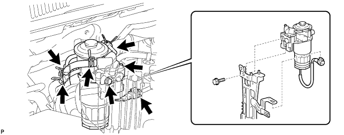
21. REMOVE FUEL FILTER ASSEMBLY
  1. Disconnect the level warning switch connector.

  1. Disconnect the 4 hoses indicated in the illustration.

  1. Remove the bolt and fuel filter.

    A125342


22. REMOVE AIR CLEANER BRACKET

  1. A124933
    Remove the glow plug relay.

  1. Disconnect the fuel filter level switch connector.

  1. A124934
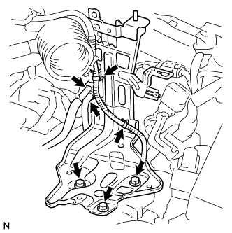
    Disconnect the 2 wire harness clamps.

  1. Disconnect the 2 fuel hoses from the bracket.

  1. Remove the 3 bolts and bracket.


23. DISCONNECT HOSES AND CONNECTORS
  1. Remove the engine room junction block cover (upper).

  1. Remove the nut and disconnect the engine room junction block cover (side) with 3 connectors and wire.

  1. Remove the nut and disconnect the starter wire.

  1. Disconnect the 2 injector driver connectors.

  1. Disconnect the vacuum pump hose.

  1. Disconnect the 2 fuel hoses.

  1. Disconnect the 2 heater hoses.

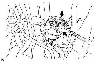
  1. Disconnect the 2 ECM connectors.

  1. Remove the 3 bolts, vacuum switching valve bracket and vacuum transmitting pipe.


24. REMOVE ECM

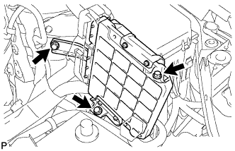
  1. A124570
    Remove the 3 bolts holding the ECM brackets.

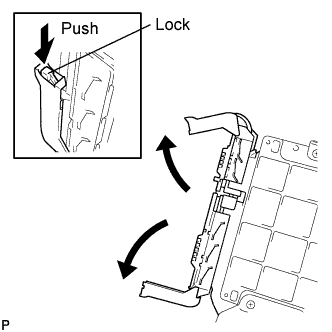
  1. A124571E01
    Disconnect the 2 ECM connectors.

    1. Raise the 2 levers while pushing the locks on the 2 levers, and remove the 2 ECM connectors.

  1. Remove the ECM.

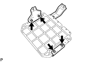
  1. A124573
    Remove the 4 screws and 2 ECM brackets.


25. REMOVE RADIATOR RESERVE TANK ASSEMBLY

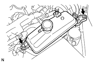
  1. A124930
    Remove the 2 bolts and reservoir.


26. REMOVE FRONT BUMPER
  1. Remove the front bumper (Click here).


27. REMOVE FRONT BUMPER REINFORCEMENT SUB-ASSEMBLY UPPER
  1. Disconnect the 2 horn connectors.
  1. Remove the 2 bolts and reinforcement.


28. REMOVE RADIATOR SUPPORT UPPER BRACKET

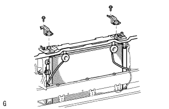
  1. E126555
    Remove the 2 bolts and 2 brackets.

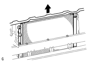
29. REMOVE COOLER CONDENSER ASSEMBLY
  1. B135838
    Remove the cooler condenser.


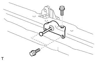
30. REMOVE HOOD LOCK ASSEMBLY

  1. B127322
    Remove the 3 bolts and hood lock striker.


31. REMOVE RADIATOR SUPPORT UPPER

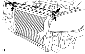
A127758
  1. Remove the 4 bolts and radiator support upper.


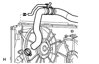
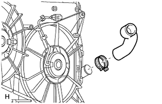
32. DISCONNECT RADIATOR HOSE INLET

A127743
  1. Remove the inlet radiator hose and No. 5 water by-pass hose from the radiator.


33. DISCONNECT RADIATOR HOSE OUTLET

A127742
  1. Remove the outlet radiator hose from the radiator.


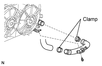
34. REMOVE RADIATOR AND INTERCOOLER

  1. A123562E01
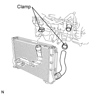
    Loosen the 2 clamps.

  1. Disconnect the No. 2 and No. 3 air hoses from the engine.

  1. Remove the radiator (with intercooler) from the vehicle.

  1. A123565E01
    Loosen the 2 clamps.

  1. Remove the bolt.

  1. Remove the No. 2 air tube from the intercooler and No. 3 air hose.

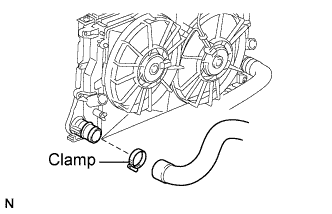
  1. A123566E01
    Loosen the clamp. Remove the No. 2 air hose from the intercooler.

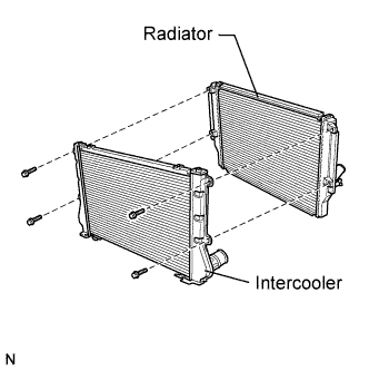
  1. A123563E01
    Remove the 4 bolts, and then separate the intercooler and radiator.


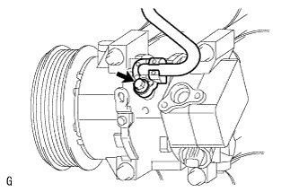
35. REMOVE DISCHARGE HOSE SUB-ASSEMBLY

  1. H102038
    Remove the bolt and disconnect the cooler refrigerant discharge hose from the cooler compressor.

  1. Remove the O-ring from the cooler refrigerant discharge hose.

    NOTICE:
    Seal the openings of the disconnected parts using vinyl tape to prevent moisture and foreign matter from entering them.


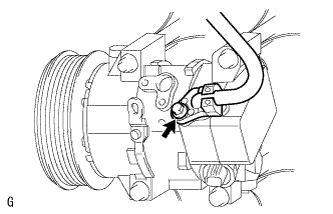
36. DISCONNECT SUCTION HOSE SUB-ASSEMBLY

  1. H102041
    Remove the bolt and disconnect the cooler refrigerant suction hose from the cooler compressor.

  1. Remove the O-ring from the cooler refrigerant suction hose.

    NOTICE:
    Seal the openings of the disconnected parts using vinyl tape to prevent moisture and foreign matter from entering them.


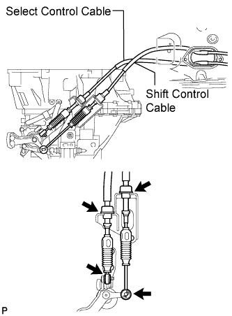
37. DISCONNECT TRANSMISSION CONTROL CABLE ASSEMBLY

C127238E02
  1. Removal the 2 clips and washers, and disconnect the top ends of the control cable from the transaxle.

  1. Remove the 2 clips and disconnect the control cable bracket.

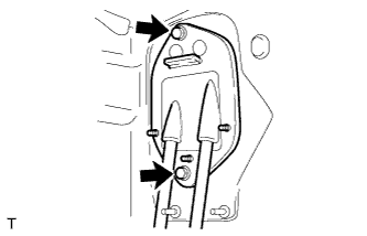
  1. C127242
    Remove the 2 bolts from the retainer.

  1. Pull out the control cable from the floor.


38. DISCONNECT CLUTCH RELEASE CYLINDER ASSEMBLY

  1. A123605
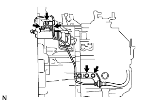
    Disconnect the 5 bolts, release cylinder and flexible hose bracket.


39. REMOVE FRONT EXHAUST PIPE ASSEMBLY
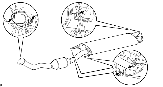
  1. Remove the 2 bolts and 2 compression springs.

  1. Disconnect the 3 exhaust pipe supports, and remove the front exhaust pipe.

  1. Remove the gasket from the exhaust manifold.

    A126833


40. REMOVE PROPELLER WITH CENTER BEARING SHAFT ASSEMBLY

  1. C127524
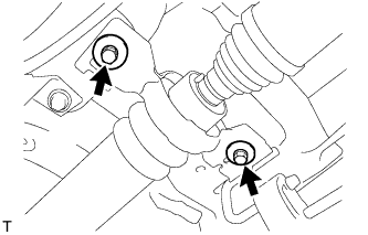
    Remove the 2 bolts and 2 adjusting washers, and disconnect the propeller with center bearing shaft.

    NOTICE:
    1. During the removal, do not exert excessive force on the universal joint.
    2. When removing, transporting or storing the propeller with center bearing shaft assembly, do not allow the No. 2 joint angle to exceed 20°.

  1. C127525E01
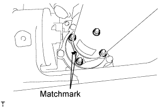
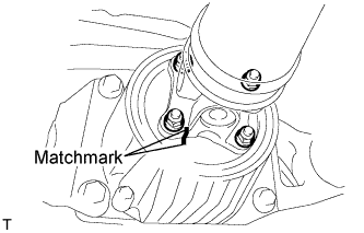
    Place matchmarks on the differential carrier and propeller shaft.

  1. Remove the 4 nuts and 4 washers, and disconnect the propeller shaft and differential carrier.

  1. C127526E01
    Place matchmarks on the transfer and propeller shaft.

  1. Remove the 4 nuts and 4 washers, and disconnect the propeller shaft from the transfer.


41. REMOVE FRONT WHEELS

42. REMOVE FRONT AXLE SHAFT LH NUT

C129483E01
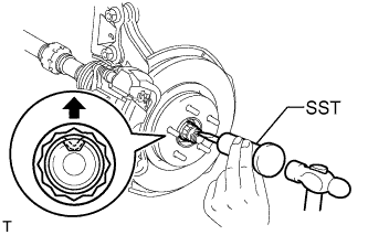
  1. Using SST and a hammer, unstake the staked part of the nut.

    SST
    09930-00010  

    NOTICE:
    Loosen the staked part of the nut completely, otherwise the screw of the drive shaft may be damaged.

  1. While applying the brakes, remove the lock axle hub nut.


43. REMOVE FRONT AXLE SHAFT RH NUT

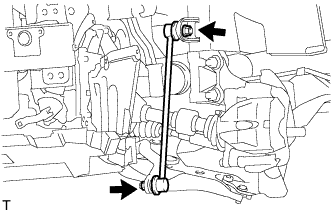
44. DISCONNECT FRONT STABILIZER LINK ASSEMBLY LH

  1. C127528
    Remove the 2 nuts and stabilizer link.


45. DISCONNECT FRONT STABILIZER LINK ASSEMBLY RH
  1. Remove the stabilizer link (Click here).


46. DISCONNECT STEERING INTERMEDIATE SHAFT
  1. (Click here).


47. DISCONNECT TIE ROD END SUB-ASSEMBLY RH

HINT:
Use the same procedure described for the No. 2 tie rod end sub-assembly.


48. DISCONNECT TIE ROD END SUB-ASSEMBLY LH

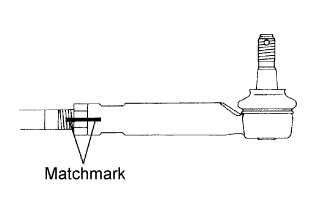
  1. F040050E19
    Put matchmarks on the No. 2 tie rod end subassembly and rack end.

  1. Remove the No. 2 tie rod end sub-assembly and lock nut.


49. REMOVE FRONT DRIVE SHAFT LH
  1. Remove the drive shaft (Click here).


50. REMOVE FRONT DRIVE SHAFT RH
  1. Remove the drive shaft (Click here).


51. REMOVE ENGINE WITH TRANSAXLE

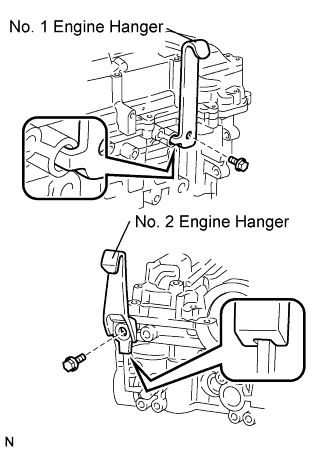
  1. A123606E01
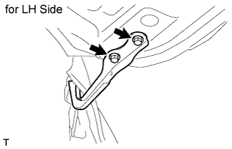
    Install the No. 1 and No. 2 engine hangers with the 2 bolts as shown in the illustration.

    Torque:
    40 N*m{ 408 kgf*cm , 30 ft.*lbf }

    Part name
    Part No.
    No. 1 engine hanger
    12281-26050 (None)
    or
    12281-26060 (Green)
    No. 2 engine hanger
    12282-26010 (None)
    or
    12282-26020 (Green)
    Bolt
    91552-81025
    or
    90105-W0042

    HINT:
    1. Insert the claw of the No. 1 engine hanger into hole of the cylinder head.
    2. Fit the fork part of the No. 2 engine hanger onto the rib of the cylinder head.

  1. Install an engine sling device to the engine and hold the engine with a chain block.

    CAUTION:
    Do not raise the engine more than necessary. If the engine is raised excessively, the vehicle may also be lifted up.

  1. Set an engine lifter underneath the engine.

  1. Remove the column hole cover. Loosen the bolt holding the intermediate shaft, and slide the intermediate shaft.

  1. Put matchmarks on the intermediate shaft and pinion.

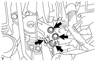
  1. A123578
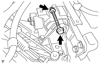
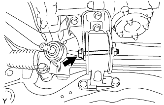
    Remove the 2 bolts and 2 nuts and disconnect the engine mounting insulator RH.

  1. A123579
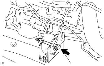
    Remove the bolt and nut, and disconnect the engine mounting insulator LH.

  1. A123580
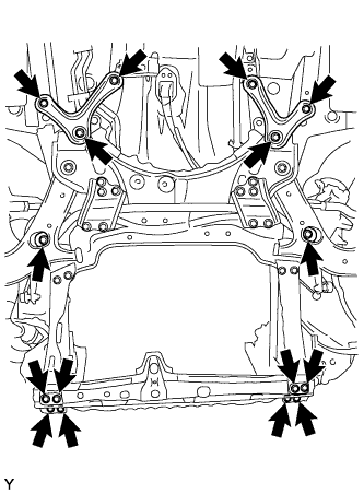
    Remove the 6 bolts and the front suspension member brace rear RH and LH.

  1. Remove the 6 bolts, crossmember and suspension member.

  1. Using the chain block, slowly remove the engine from the vehicle and the intermediate shaft from the pinion. Then set the engine on the engine lifter.

    NOTICE:
    1. Make sure that the engine is clear of all wiring and hoses.
    2. While lowering the engine from the vehicle, do not allow it to contact the vehicle.

    HINT:
    Place the engine on wooden blocks or equivalent so that the engine is level.

  1. Remove the sling device from the engine.


52. REMOVE FRONT CROSSMEMBER SUB-ASSEMBLY
  1. Install a chain block.

  1. A123581
    Remove the bolt, nut and crossmember.


53. REMOVE FRONT SUSPENSION CROSSMEMBER SUB-ASSEMBLY

  1. A123582
    Remove the bolt and suspension crossmember.


54. REMOVE NO. 1 AIR TUBE

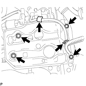
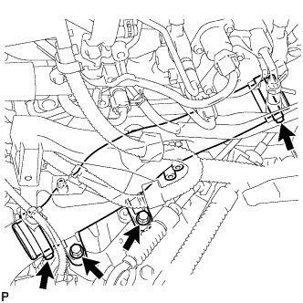
  1. A124904
    Remove the 2 bolts and disconnect the wire harness.

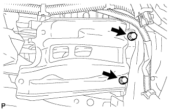
  1. A124905
    Remove the 2 bolts and loosen the 2 clamps.

  1. Remove the No. 1 air tube.


55. REMOVE ENGINE WIRE
  1. Remove the engine wire from the engine.


56. REMOVE STARTER ASSEMBLY

  1. A163980
    Disconnect the starter connector.

  1. Open the terminal cap, remove the nut and disconnect the starter wire.

  1. A163979
    Remove the 2 bolts and starter.


57. REMOVE OIL PAN INSULATOR

58. REMOVE STIFFENER PLATE RH

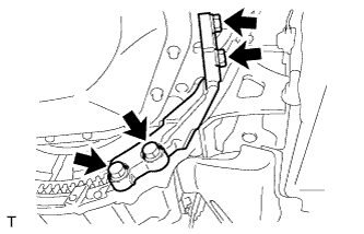
C127241
  1. Remove the 4 bolts and stiffener plate from the engine and transaxle assembly.


59. REMOVE STIFFENER PLATE LH

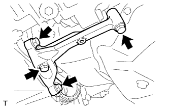
C127240
  1. Remove the 4 bolts and stiffener plate from the engine and transaxle assembly.


60. REMOVE MANUAL TRANSAXLE ASSEMBLY

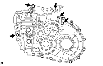
C112442
  1. Remove the 5 bolts.

  1. Separate and remove the transaxle from the engine.


61. REMOVE CLUTCH DISC ASSEMBLY

NOTICE:
Keep the lining part of the clutch disc, the pressure plate and the surface of the flywheel away from oil and foreign matter.


62. REMOVE FLYWHEEL SUB-ASSEMBLY

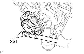
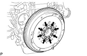
  1. A111238E01
    Hold the crankshaft with SST.
    SST
    09213-58013  
    09330-00021  

  1. A111255
    Using a T55 "torx" socket wrench, remove the 8 bolts and the flywheel.


63. INSTALL ENGINE STAND
  1. Remove the sling device and chain block from the engine.


64. REMOVE FAN AND GENERATOR V BELT

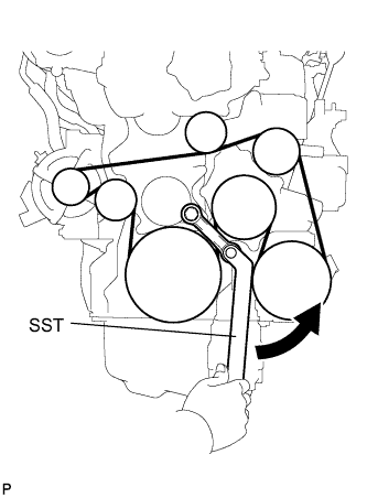
  1. A123517E02
    Using SST and 22 mm wrench, rotate the tensioner pulley counterclockwise to loosen the belt tension. Then remove the V-ribbed belt.
    SST
    09216-42010  

    NOTICE:
    Make sure SST is installed as shown in the illustration. If not, SST and/or the V-ribbed belt may not be able to be removed.


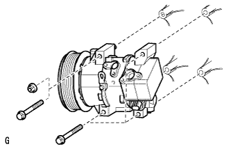
65. REMOVE COMPRESSOR WITH PULLEY ASSEMBLY

  1. E126953
    Disconnect the connector.

  1. w/o Stud Bolt:
    Remove the 4 bolts and cooler compressor.

  1. w/ Stud Bolt:
    Remove the 3 bolts, nut and cooler compressor.


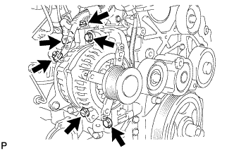
66. REMOVE GENERATOR ASSEMBLY

  1. A127719
    Disconnect the generator connector.

  1. Remove the terminal cap.

  1. Remove the nut and bolt, and disconnect the generator wire.

  1. Remove the 3 bolts and generator.


67. REMOVE NO. 2 IDLER PULLEY SUB-ASSEMBLY

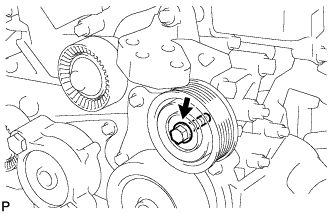
  1. A126838
    Remove the bolt, plate and idler pulley.


68. REMOVE NO. 1 IDLER PULLEY SUB-ASSEMBLY

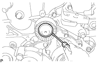
  1. A123583
    Using a screwdriver, remove the idler pulley cover plate.

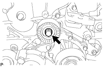
  1. A123584
    Remove the bolt and idler pulley.


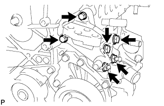
69. REMOVE TRANSVERSE ENGINE MOUNTING BRACKET

  1. A123586
    Remove the 4 bolts, 2 nuts and engine mounting bracket.


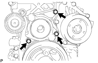
70. REMOVE V-RIBBED BELT TENSIONER ASSEMBLY

  1. A123607
    Remove the 3 bolts and tensioner.


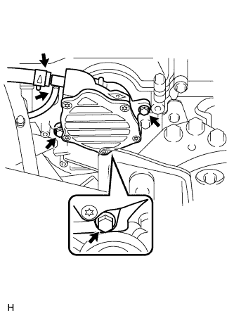
71. REMOVE VACUUM PUMP ASSEMBLY

  1. C128547
    Disconnect the 2 vacuum hoses.

  1. Remove the 3 bolts and vacuum pump.

  1. Remove the 2 O-rings from the vacuum pump.


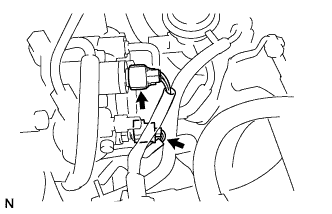
72. REMOVE INJECTION OR SUPPLY PUMP ASSEMBLY

  1. A110786
    Disconnect the fuel temperature sensor connector.

  1. Disconnect the suction control valve connector.

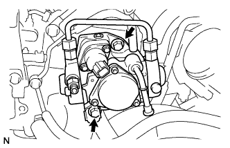
  1. A114894
    Remove the 2 bolts to remove the supply pump, O-ring and supply pump drive coupling from the cylinder head.

  1. Remove the O-ring from the supply pump.


73. REMOVE OIL DIPSTICK GUIDE

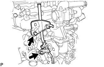
  1. A123608
    Remove the 2 bolts and oil dipstick guide.

  1. Remove the O-ring from the dipstick guide.


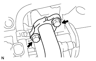
74. REMOVE NO. 2 EGR PIPE SUB-ASSEMBLY

  1. A126856
    Remove the 2 bolts.

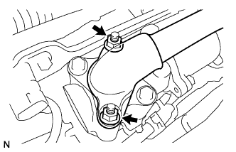
  1. A110765
    Remove the 2 nuts, EGR pipe and 2 gaskets.


75. REMOVE EGR VALVE ASSEMBLY
  1. Disconnect the EGR valve connector.

  1. A110766
    Disconnect the EGR valve connector.

  1. A126857
    Remove the 2 bolts, EGR valve and gasket.


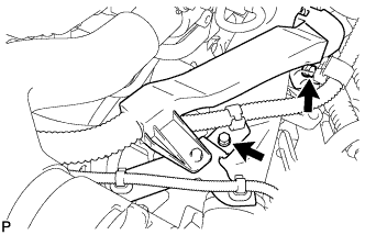
76. REMOVE ENGINE COVER BRACKET
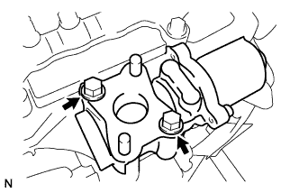
  1. Remove the bolt and pressure sensor.

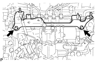
  1. A123585
    Remove the 2 bolts and engine cover bracket.


77. REMOVE COMMON RAIL ASSEMBLY
  1. Remove the common rail (Click here).


78. REMOVE INJECTOR ASSEMBLY
  1. Remove the injector (Click here).


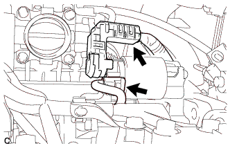
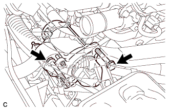
79. REMOVE DIESEL THROTTLE BODY ASSEMBLY

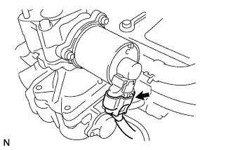
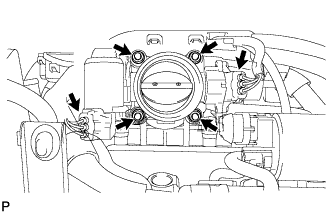
  1. A124890
    Disconnect the throttle position sensor connector.

  1. Disconnect the throttle motor connector.

  1. Remove the 2 nuts and 2 bolts, and then remove the diesel throttle body and gasket.


80. REMOVE INTAKE MANIFOLD

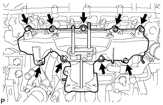
  1. A111247
    Remove the 7 bolts, 2 nuts, intake manifold and gasket.


81. REMOVE OIL COOLER ASSEMBLY

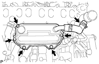
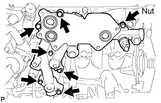
  1. A111248
    Disconnect the oil cooler hose.

  1. Remove the 5 bolts, 3 O-rings and oil cooler.


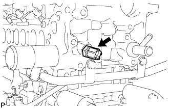
82. REMOVE DIESEL ENGINE COOLANT TEMPERATURE SENSOR

  1. A111258
    Remove the engine coolant temperature sensor.


83. REMOVE NO. 3 WATER BY-PASS PIPE

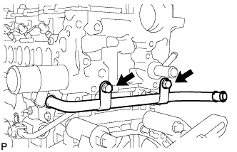
  1. A123609
    Remove the 2 bolts, O-ring and by-pass pipe.


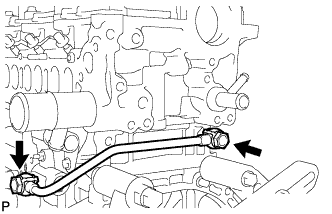
84. REMOVE NO. 1 TURBO OIL PIPE

  1. A111250
    Remove the 2 union bolts, 2 gaskets and oil pipe.


85. REMOVE NO. 1 OIL COOLER BRACKET

  1. A111252E05
    Remove the 6 bolts, nut and oil cooler bracket.

  1. Remove the 3 O-rings.


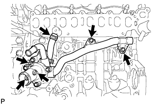
86. REMOVE WATER INLET HOUSING

  1. A111253
    Remove the 2 bolts, O-ring and by-pass pipe.

  1. Disconnect the hose.

  1. Remove the 3 nuts, gasket and inlet housing.


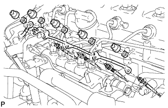
87. REMOVE GLOW PLUG ASSEMBLY

  1. A124901
    Remove the 5 grommets.

  1. Remove the 5 nuts and glow plug connector.

  1. Remove the 4 glow plugs.


88. REMOVE TURBOCHARGER SUB-ASSEMBLY
  1. Remove the turbocharger (Click here).


89. REMOVE DRIVE SHAFT BEARING BRACKET

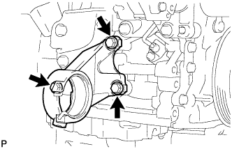
  1. A129523
    Remove the 3 bolts and bearing bracket.


90. REMOVE EGR COOLER ASSEMBLY

  1. A110787
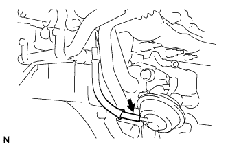
    Disconnect the vacuum hose from the No. 2 EGR valve.

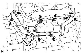
  1. A114995
    Remove the 4 bolts.

  1. Remove the 2 bolts, 2 nuts, EGR cooler, 2 gaskets and O-ring.

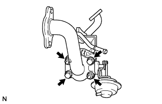
  1. A114901
    Remove the 2 bolts and 2 nuts.

  1. Disassemble the No. 1 EGR pipe, No. 2 EGR valve, EGR cooler and 2 gaskets.


91. REMOVE EXHAUST MANIFOLD

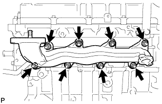
  1. A111244
    Remove the 8 nuts, 8 collars, exhaust manifold and gasket.


92. REMOVE ENGINE OIL LEVEL SENSOR

  1. A123531
    Remove the 4 bolts and level sensor.

← REMOVAL (Nov 2005 – Dec 2006)REMOVAL (from Aug 2007) →