7.
REMOVE PROPELLER WITH CENTER BEARING SHAFT ASSEMBLY
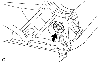
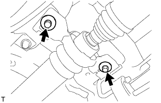
Remove the 2 bolts and 2 adjusting washers, and disconnect the propeller with center bearing shaft.
NOTICE:
During the removal, do not exert excessive force on the universal joint.
When removing, transporting or storing the propeller with center bearing shaft assembly, do not allow the No. 2 joint angle to exceed 20°.
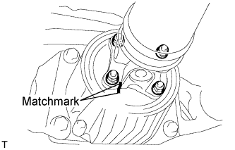
Place matchmarks on the differential carrier and propeller shaft.
Remove the 4 nuts and 4 washers, and disconnect the propeller shaft and differential carrier.
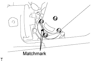
Place matchmarks on the transfer and propeller shaft.
Remove the 4 nuts and 4 washers, and disconnect the propeller shaft from the transfer.
8.
REMOVE REAR AXLE SHAFT NUT
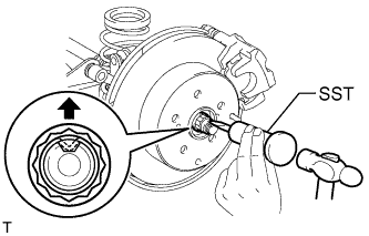
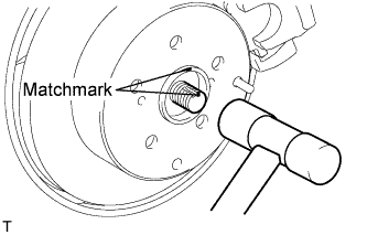
Using SST and hammer, unstake the staked part of the nut.
SST
09930-00010
NOTICE:
Loosen the staked part of the nut completely, otherwise the screw of the drive shaft may be damaged.
While applying the brake, remove the lock axle hub nut.
9.
DISCONNECT DIFFERENTIAL CARRIER ASSEMBLY
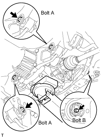
Support the rear differential carrier with a transmission jack or equivalent.
Fix the nuts in place and remove bolt A, bolt B and bolt C.
NOTICE:
Do not loosen the nuts. Loosen the bolts.
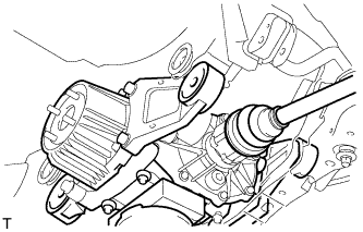
Slowly lower the jack and then tilt the rear differential carrier as shown in the illustration.
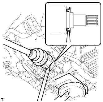
Set the tip of the tire lever to the position on the rear drive shaft inboard joint shown in the illustration. Then, using the ribbed part of the rear differential carrier as a fulcrum, disconnect the left and right rear drive shafts.
Put matchmarks on the drive shaft and the axle hub.
NOTICE:
Do not punch the marks.
Using a plastic-faced hammer, separate the drive shaft from the axle hub.
NOTICE:
Be careful not to damage the boot and speed sensor rotor. Do not excessively push out the drive shaft from the axle.
12.
FIX FRONT AXLE ASSEMBLY
NOTICE:
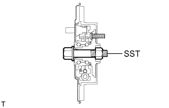
The hub bearing could be damaged if it is subjected to the vehicle weight, such as when moving the vehicle with the drive shaft removed. Therefore, if it is absolutely necessary to place the vehicle weight on the hub bearing, first support it with SST.