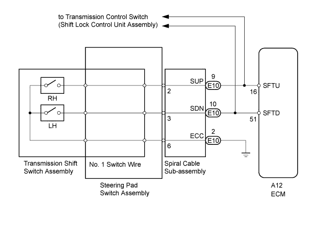
CONTINUOUSLY VARIABLE TRANSAXLE SYSTEM > Shift Paddle Switch Circuit |
| 1.CHECK HARNESS AND CONNECTOR (SPIRAL CABLE - BODY GROUND) |
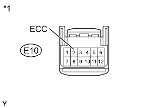 |
Disconnect the spiral cable connector.
Measure the resistance according to the value(s) in the table below.
| Tester Connection | Condition | Specified Condition |
| E10-2 (ECC) - Body ground | Always | Below 1 Ω |
| *1 | Front view of wire harness connector (to Spiral Cable Sub-assembly) |
|
| ||||
| OK | |
 |
| 2.INSPECT SPIRAL CABLE SUB-ASSEMBLY |
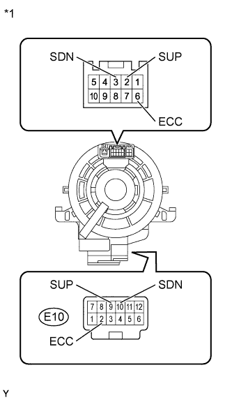 |
Remove the spiral cable sub-assembly (Click here).
Measure the resistance according to the value(s) in the table below.
| Tester Connection | Condition | Specified Condition |
| 2 (SUP) - E10-9 (SUP) | Always | Below 1 Ω |
| 3 (SDN) - E10-10 (SDN) | Always | Below 1 Ω |
| 6 (ECC) - E10-2 (ECC) | Always | Below 1 Ω |
| *1 | Component without harness connected (Spiral Cable Sub-assembly) |
|
| ||||
| OK | |
|
| 3.INSPECT TRANSMISSION SHIFT SWITCH ASSEMBLY (LH (-) AND RH (+)) |
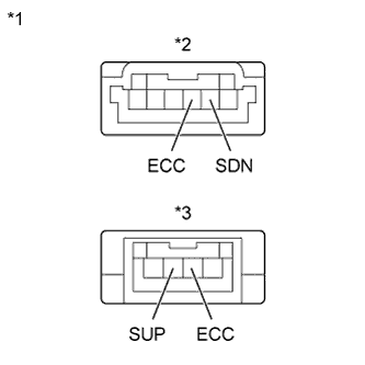 |
Remove the transmission shift switch assembly (Click here).
Measure the resistance according to the value(s) in the table below.
| Tester Connection | Switch Condition | Specified Condition |
| SDN - ECC | "-" shift paddle operated and held (down-shift) | Below 2.5 Ω |
| SDN - ECC | "-" shift paddle not operated (down-shift) | 1 MΩ or higher |
| Tester Connection | Switch Condition | Specified Condition |
| SUP - ECC | "+" shift paddle operated and held (up-shift) | Below 2.5 Ω |
| SUP - ECC | "+" shift paddle not operated (up-shift) | 1 MΩ or higher |
| *1 | Component without harness connected (Transmission Shift Switch Assembly) |
| *2 | for LH |
| *3 | for RH |
|
| ||||
| OK | |
|
| 4.INSPECT NO. 1 SWITCH WIRE |
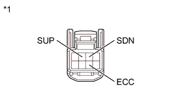 |
Disconnect the No. 1 switch wire connector.
Measure the resistance according to the value(s) in the table below.
| Tester Connection | Switch Condition | Specified Condition |
| SDN - ECC | "-" shift paddle operated and held (down-shift) | Below 2.5 Ω |
| SUP - ECC | "+" shift paddle operated and held (up-shift) | Below 2.5 Ω |
| SDN - ECC | "-" shift paddle not operated (down-shift) | 1 MΩ or higher |
| SUP - ECC | "+" shift paddle not operated (up-shift) | 1 MΩ or higher |
| *1 | Component without harness connected (No. 1 Switch Wire) |
|
| ||||
| OK | |
|
| 5.INSPECT STEERING PAD SWITCH ASSEMBLY |
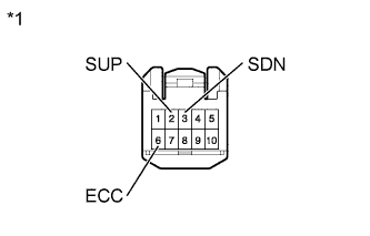 |
Disconnect the steering pad switch assembly connector.
Measure the resistance according to the value(s) in the table below.
| Tester Connection | Switch Condition | Specified Condition |
| 2 (SUP) - 6 (ECC) | "+" shift paddle operated and held (up-shift) | Below 2.5 Ω |
| 3 (SDN) - 6 (ECC) | "-" shift paddle operated and held (down-shift) | Below 2.5 Ω |
| 2 (SUP) - 6 (ECC) | "+" shift paddle not operated (up-shift) | 1 MΩ or higher |
| 3 (SDN) - 6 (ECC) | "-" shift paddle not operated (down-shift) | 1 MΩ or higher |
| *1 | Front view of wire harness connector (to Spiral Cable Sub-assembly) |
|
| ||||
| OK | |
|
| 6.CHECK HARNESS AND CONNECTOR (SPIRAL CABLE - ECM) |
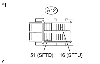 |
Disconnect the ECM connector.
Disconnect the transmission control switch (shift lock control unit assembly) connector.
Measure the resistance according to the value(s) in the table below.
| Tester Connection | Switch Condition | Specified Condition |
| A12-16 (SFTU) - Body ground | "+" shift paddle operated and held (up-shift) | Below 2.5 Ω |
| A12-51 (SFTD) - Body ground | "-" shift paddle operated and held (down-shift) | Below 2.5 Ω |
| A12-16 (SFTU) - Body ground | "+" shift paddle not operated (up-shift) | 1 MΩ or higher |
| A12-51 (SFTD) - Body ground | "-" shift paddle not operated (down-shift) | 1 MΩ or higher |
| *1 | Front view of wire harness connector (to ECM) |
|
| ||||
| OK | |
|
| 7.REPLACE ECM |
Replace the ECM (Click here).
| NEXT | |
|
| 8.PERFORM INITIALIZATION |
| Replaced Part |
|
Using the intelligent tester, perform reset memory, deceleration sensor 0 point calibration and CVT oil pressure calibration (Click here).
Check that no DTC is stored.
| NEXT | ||
 | ||
| ||
