DRIVE SHAFT / PROPELLER SHAFT FRONT DRIVE SHAFT ASSEMBLY(for AWD) INSTALLATION
PROCEDURE

 1.INSTALL FRONT DRIVE SHAFT HOLE SNAP RING LH
Install a new front drive shaft hole snap ring LH.
2.INSTALL FRONT DRIVE SHAFT ASSEMBLY LH
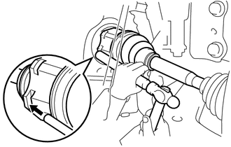
Coat the spline of the inboard joint shaft assembly with MP grease.
Set the front drive shaft hole snap ring LH with the opening side facing down.
Align the splines and tap in the front drive shaft assembly with a brass bar and hammer.
- NOTICE:
- ·
Using MP grease, set the front drive shaft hole snap ring in the groove with the opening facing downwards and centered radially.
·Be careful not to damage the oil seal, front axle inboard joint boot and front drive shaft dust cover.
3.INSTALL FRONT DRIVE SHAFT ASSEMBLY RH
Install a new drive shaft bearing bracket hole snap ring to the front drive shaft assembly RH.
Align the shaft splines and securely install the front drive shaft assembly RH.
- NOTICE:
- ·
Be careful not to damage the transaxle case oil seal, inboard joint boot and drive shaft dust cover.
·When inserting the front drive shaft assembly RH, keep it level.
Install the drive shaft bearing bracket hole snap ring and a new bolt.
- Torque:
- 32.4 N*m (330 kgf*cm, 24 ft.*lbf)
4.CONNECT STEERING KNUCKLE WITH AXLE HUB LH
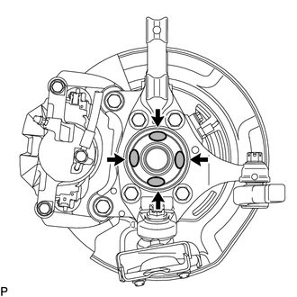
Apply MP grease to the entire contact surface between the front drive shaft assembly and axle hub bearing surface or only apply 0.1 to 0.3 g (0.00353 to 0.0105 oz.) of MP grease to the 4 areas on the axle hub bearing shown in the illustration.
Align the matchmarks and connect the steering knuckle with axle hub LH.
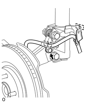
Attach the 2 guides and install the bolt.
- Torque:
- 18.5 N*m (189 kgf*cm, 14 ft.*lbf)
5.CONNECT STEERING KNUCKLE WITH AXLE HUB RH
- HINT:
-
Use the same procedure described for the LH side.
6.CONNECT FRONT LOWER NO. 1 SUSPENSION ARM SUB-ASSEMBLY LH
7.CONNECT FRONT LOWER NO. 1 SUSPENSION ARM SUB-ASSEMBLY RH
- HINT:
-
Use the same procedure described for the LH side.
8.INSTALL FRONT STABILIZER LINK ASSEMBLY LH
9.INSTALL FRONT STABILIZER LINK ASSEMBLY RH
- HINT:
-
Use the same procedure described for the LH side.
10.CONNECT FRONT SPEED SENSOR LH
11.CONNECT FRONT SPEED SENSOR RH
- HINT:
-
Use the same procedure described for the LH side.
12.INSTALL FRONT AXLE SHAFT NUT LH
13.INSTALL FRONT AXLE SHAFT NUT RH
- HINT:
-
Use the same procedure described for the LH side.
14.ADD AUTOMATIC TRANSAXLE FLUID
15.ADD TRANSFER OIL
16.INSPECT FOR OIL LEAK
17.INSTALL REAR ENGINE UNDER COVER RH
18.INSTALL REAR ENGINE UNDER COVER LH
19.INSTALL NO. 1 ENGINE UNDER COVER
20.INSTALL FRONT WHEEL
- Torque:
- 103 N*m (1050 kgf*cm, 76 ft.*lbf)
21.CHECK SPEED SENSOR SIGNAL
22.INSPECT AND ADJUST FRONT WHEEL ALIGNMENT