2AR-FE ENGINE CONTROL SFI SYSTEM(w/ Canister Pump Module) ACIS Control Circuit
DESCRIPTION
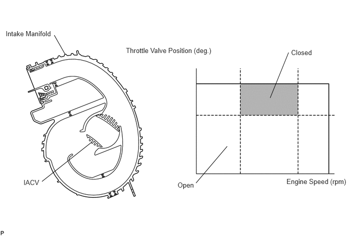
This circuit opens and closes the Intake Air Control Valve (IACV) according to the engine load in order to increase intake efficiency (ACIS: Acoustic Control Induction System).
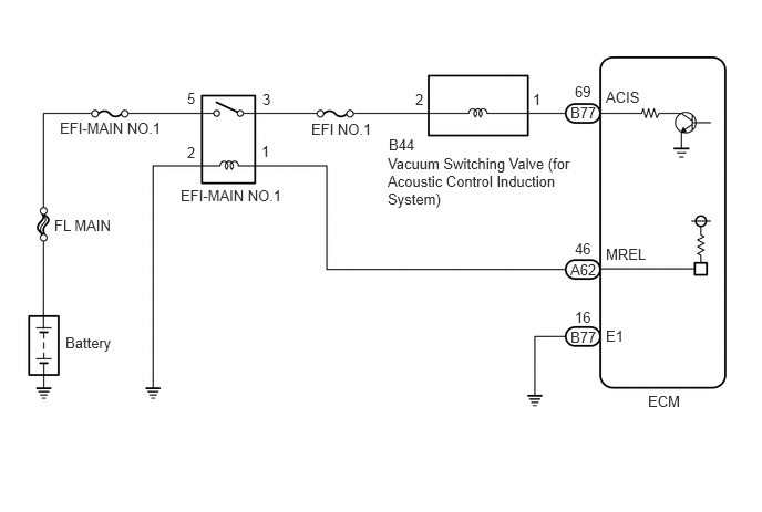
WIRING DIAGRAM
CAUTION / NOTICE / HINT
- NOTICE:
-
Inspect the fuses for circuits related to this system before performing the following procedure.
PROCEDURE
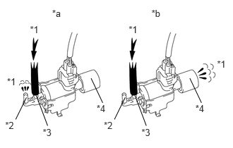
| *1 | Air |
| *2 | Port F |
| *3 | Port E |
| *4 | Air Filter |
| *a | Vacuum Switching Valve Assembly is ON |
| *b | Vacuum Switching Valve Assembly is OFF |
Disconnect the vacuum hose from port F of the vacuum switching valve assembly (for acoustic control induction system).
Connect the GTS to the DLC3.
Start the engine.
Enter the following menus: Powertrain / Engine and ECT / Active Test / Active the VSV for Intake Control.
- Powertrain > Engine and ECT > Active Test
-
Tester Display Activate the VSV for Intake Control - 50004 234 3
Operate the vacuum switching valve assembly for acoustic control induction system.
Check the vacuum switching valve assembly air flow when switching the vacuum switching valve assembly.
- OK:
Test Condition Specified Condition Vacuum switching valve assembly is ON Air from port E flows out through port F Vacuum switching valve assembly is OFF Air from port E flows out through air filter
- Result:
Proceed to OK NG
OK
NG
Check the vacuum hoses.
Click hereEngine / Hybrid System>2AR-FE INTAKE / EXHAUST>INTAKE SYSTEM>ON-VEHICLE INSPECTION
- Result:
Proceed to OK NG
OK
NG
Inspect the intake air control valve (for acoustic control induction system).
Click hereEngine / Hybrid System>2AR-FE INTAKE / EXHAUST>INTAKE MANIFOLD>INSPECTION
- Result:
Proceed to OK NG
OK
NG
Inspect the vacuum switching valve assembly (for acoustic control induction system).
- Result:
Proceed to OK NG
OK
NG
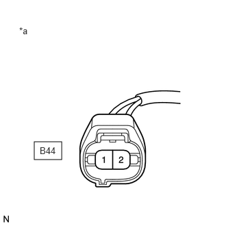
| *a | Front view of wire harness connector
(to Vacuum Switching Valve Assembly (for ACIS)) |
Disconnect the vacuum switching valve assembly connector.
Turn the ignition switch to ON.
Measure the voltage according to the value(s) in the table below.
- Standard Voltage:
Tester Connection Switch Condition Specified Condition B44-2 - Body ground Ignition switch ON 11 to 14 V
- Result:
Proceed to OK NG
OK
NG
Disconnect the vacuum switching valve assembly connector.
Disconnect the ECM connector.
Measure the resistance according to the value(s) in the table below.
- Standard Resistance:
Tester Connection Condition Specified Condition B44-1 - B77-69 (ACIS) Always Below 1 Ω B44-1 or B77-69 (ACIS) - Body ground Always 10 kΩ or higher
- Result:
Proceed to OK NG
OK
NG
Remove the EFI-MAIN No. 1 relay from the engine room relay block and junction block assembly.
Disconnect the vacuum switching valve assembly connector.
Measure the resistance according to the value(s) in the table below.
- Standard Resistance:
Tester Connection Condition Specified Condition EFI-MAIN NO. 1 relay terminal 3 - B44-2 Always Below 1 Ω EFI-MAIN NO. 1 relay terminal 3 or B44-2 - Body ground Always 10 kΩ or higher
- Result:
Proceed to OK NG
OK
NG