CLUTCH CLUTCH MASTER CYLINDER(for RHD) INSTALLATION
PROCEDURE

 31415
1.INSTALL CLUTCH MASTER CYLINDER GASKET
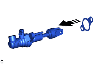
Install a new clutch master cylinder gasket to the clutch master cylinder assembly.
31410
2.INSTALL CLUTCH MASTER CYLINDER ASSEMBLY
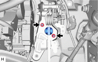
Install the clutch master cylinder assembly to the vehicle body with the 2 nuts.
- Torque:
- 12.7 N*m (130 kgf*cm, 9 ft.*lbf)
31453A
3.CONNECT CLUTCH MASTER CYLINDER PUSH ROD CLEVIS WITH HOLE PIN
31481
4.CONNECT CLUTCH MASTER CYLINDER TO FLEXIBLE HOSE TUBE
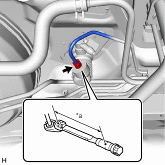
| *a | Torque Wrench Fulcrum Length |
Using a union nut wrench, connect the clutch master cylinder to flexible hose tube.
- Torque:
- Specified tightening torque : 15.2 N*m (155 kgf*cm, 11 ft.*lbf)
- HINT:
- ·
Calculate the torque wrench reading when changing the fulcrum length of the torque wrench.
(Click hereGeneral>INTRODUCTION>REPAIR INSTRUCTION>PRECAUTION)
·When using a union nut wrench (fulcrum length of 22 mm (0.866 in.)) + torque wrench (fulcrum length of 162 mm (6.378 in.)): 13.4 N*m (137 kgf*cm, 10 ft.*lbf)
31434E
5.CONNECT NO. 1 CLUTCH RESERVOIR HOSE
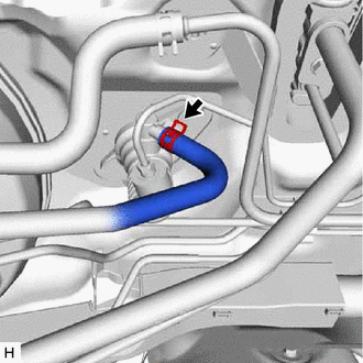
Connect the clutch reservoir hose to the clutch master cylinder assembly, and slide the hose clip to secure it.
- NOTICE:
-
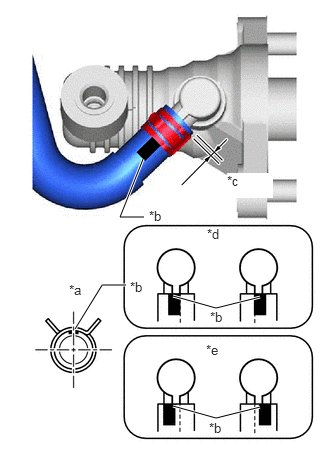 1.5,2.26 1.25,2.26 1.25,2.26 1.49,1.656 true 2.708,3.094 2.25,3.208 2.25,3.208 1.802,3.083 true 1.313,2.969 1.063,2.969 1.063,2.969 0.781,3.427 true 2.708,4.24 2.25,4.354 2.25,4.354 1.802,4.229 true 0.719,2.938 1.031,3.094 0.313,0.156 10 false *a 1.354,2.906 1.667,3.063 0.313,0.156 10 false *b 2.365,1.802 2.844,2.063 0.479,0.26 10 true *c 2.156,2.354 2.469,2.51 0.313,0.156 10 false *d 2.146,3.563 2.458,3.719 0.313,0.156 10 false *e 2.188,3.219 2.5,3.375 0.313,0.156 10 false *b 1.552,2.167 1.865,2.323 0.313,0.156 10 false *b 2.177,4.375 2.49,4.531 0.313,0.156 10 false *b
*a Top of Vehicle *b Paint Mark *c 0 to 2 mm (0 to 0.0787 in.) *d OK *e NG
- ·
Make sure that the paint mark of the clutch reservoir hose is within the location shown in the illustration.
·Make sure that the claws of the hose clip are within the location shown in the illustration.
·Connect the clutch reservoir hose so that it will not be twisted.
·Face the yellow mark upward.
6.INSTALL KNEE AIRBAG ASSEMBLY (for Driver Side)
7.CHECK SRS WARNING LIGHT
8.BLEED CLUTCH PIPE LINE
Click hereDrivetrain>CLUTCH>CLUTCH SYSTEM>BLEEDING
9.INSPECT FOR BRAKE FLUID LEAK
- HINT:
- ·
Check for leakage in the brake system.
·Check for leakage in the clutch system.
10.CHECK FLUID LEVEL IN RESERVOIR
31301
11.INSPECT AND ADJUST CLUTCH PEDAL SUB-ASSEMBLY