FRONT SUSPENSION FRONT STABILIZER BAR REMOVAL
CAUTION / NOTICE / HINT
The necessary procedures (adjustment, calibration, initialization, or registration) that must be performed after parts are removed and installed, or replaced during front stabilizer bar removal/installation are shown below.
| Replaced Part or Performed Procedure | Necessary Procedure | Effect/Inoperative Function when Necessary Procedure not Performed | Link |
|---|---|---|---|
|
*: When performing learning using the GTS. Click here( |
|||
| Auxiliary battery terminal is disconnected/reconnected | Perform steering sensor zero point calibration | Lane control system | ( ) |
| Parking support brake system (for HV model)* | |||
| Pre-collision system | |||
| Memorize steering angle neutral point | Parking assist monitor system | ()
|
|
| Panoramic view monitor system (for HV model) | ()
|
||
| Reset back door close position | Power back door system (for HV model) | ()
|
|
| Power back door initialization | Power door lock control system | ()
|
|
| ECM | w/ Canister Pump Module:
Perform Vehicle Identification Number (VIN) registration |
DTC P063051 is output | ()
|
w/o Canister Pump Module:
Perform Vehicle Identification Number (VIN) or frame number registration |
()
|
||
·
Gas leak from exhaust system is repaired ·
Replacement of air fuel ratio sensor |
Inspection after repair | ·
Poor idle, etc. ·
Engine start function, etc. |
w/ Canister Pump Module:()
w/o Canister Pump Module:( )
|
| Inverter with converter assembly | Resolver learning | ·
DTCs are stored ·
Slight vibration at a vehicle speed of 5 km/h (3 mph) or less ·
Shock or vibration during acceleration |
()
|
| Hybrid vehicle transaxle assembly | ·
Resolver learning ·
Initialize resolver |
||
| Front wheel alignment adjustment | 1.
Clear zero point calibration data. 2.
Perform yaw rate and acceleration sensor zero point calibration. |
·
DTCs are stored ·
ABS warning light illuminates ·
Brake warning light / yellow (minor malfunction) illuminates ·
Slip indicator light illuminates ·
VSC disabled or malfunctions |
()
|
| Front bumper assembly (Including removal and installation) | ·
Ultrasonic sensor detection angle ·
Ultrasonic sensor detection angle registration |
Parking support brake system (for HV model) | ()
|
| Front television camera view adjustment | Panoramic view monitor system (for HV model) | ()
|
|
| Suspension, tires, etc.
(The vehicle height changes because of suspension or tire replacement) |
·
Ultrasonic sensor detection angle ·
Ultrasonic sensor detection angle registration |
Parking support brake system (for HV model) | ()
|
| Television camera assembly optical axis (Back camera position setting) | Parking assist monitor system | ()
|
|
·
Parking assist ECU initialization ·
Adjust steering angle |
Panoramic view monitor system (for HV model) | ()
|
|
| Replacement of the headlight ECU sub-assembly LH | ·
Synchronize the vehicle information ·
Perform headlight ECU sub-assembly LH initialization |
Lighting system (EXT) | ()
|
| Rack and pinion power steering gear assembly | ·
Perform torque sensor zero point calibration ·
Assist map writing |
·
DTCs are output ·
EPS warning light illuminates |
()
|
- NOTICE:
- ·
After the ignition switch is turned off, the navigation system requires approximately a minute to record various types of memory and settings. As a result, after turning the ignition switch off, wait a minute or more before disconnecting the cable from the negative (-) auxiliary battery terminal.
·This procedure includes the removal of small-head bolts. Refer to Small-Head Bolts of Basic Repair Hint to identify the small-head bolts.
Click hereGeneral>INTRODUCTION>REPAIR INSTRUCTION>PRECAUTION
| Replaced Part or Performed Procedure | Necessary Procedure | Effect/Inoperative Function when Necessary Procedure not Performed | Link |
|---|---|---|---|
|
*1: When performing learning using the GTS. Click here( *2: w/ Gasoline Particulate Filter |
|||
| Auxiliary battery terminal is disconnected/reconnected | Drive the vehicle until stop and start control is permitted (approximately 5 to 60 minutes) | Stop and start system | for A25A-FKS:()
for M20A-FKS:( )
|
| Perform steering sensor zero point calibration | Lane control system | ()
|
|
| Parking support brake system (for Gasoline model)*1 | |||
| Pre-collision system | |||
| Memorize steering angle neutral point | Parking assist monitor system | ()
|
|
| Panoramic view monitor system (for Gasoline model) | ()
|
||
| Reset back door close position | Power back door system (for Gasoline model) | ()
|
|
| Power back door initialization | Power door lock control system | ()
|
|
| ECM | Perform Vehicle Identification Number (VIN) or frame number registration | DTC P063051 is output | A25A-FKS (w/ Canister Pump Module):()
A25A-FKS (w/o Canister Pump Module):( )
M20A-FKS:( )
|
| ECU communication ID registration | Engine start function | See Service Bulletin for the registration method. | |
for M20A-FKS:
GPF Deposition Values*2 -
GPF deposition values save -
GPF deposition values write |
·
MIL comes on ·
Deterioration of fuel efficiency |
()
|
|
for UB80E:
If transaxle compensation code read from ECM -
Perform reset memory -
Transfer transaxle compensation code -
Perform road test to allow ECM to learn |
·
Large shift shock ·
Deterioration of fuel efficiency |
for Initialization:()
for Registration:( )
|
|
for UB80F:
If transaxle compensation code read from ECM -
Perform reset memory -
Transfer transaxle compensation code -
Perform road test to allow ECM to learn |
·
Large shift shock ·
Deterioration of fuel efficiency |
for Initialization:()
for Registration:( )
|
|
for K120:
·
Perform reset memory ·
Perform road test to allow TCM to learn |
·
Large shift shock ·
Deterioration of fuel efficiency |
()
|
|
for K120F:
·
Perform reset memory ·
Perform road test to allow TCM to learn |
·
Large shift shock ·
Deterioration of fuel efficiency |
()
|
|
·
Gas leak from exhaust system is repaired ·
Replacement of air fuel ratio sensor |
Inspection after repair | ·
Poor idle, etc. ·
Engine start function, etc. |
A25A-FKS (w/ Canister Pump Module):()
A25A-FKS (w/o Canister Pump Module):( )
M20A-FKS:( )
|
for M20A-FKS:
Front exhaust pipe assembly |
GPF deposition value clear | ·
MIL comes on ·
Deterioration of fuel efficiency |
()
|
| Automatic transaxle assembly | for UB80E:
·
Reset memory ·
Input transaxle compensation code into ECM ·
Perform road test to allow ECM to learn |
·
Large shift shock ·
Deterioration of fuel efficiency |
for Initialization:()
for Registration:( )
|
for UB80F:
·
Reset memory ·
Input transaxle compensation code into ECM ·
Perform road test to allow ECM to learn |
·
Large shift shock ·
Deterioration of fuel efficiency |
for Initialization:()
for Registration:( )
|
|
| Automatic transaxle fluid | ATF thermal degradation estimate reset | The value of the Data List item "ATF Thermal Degradation Estimate" is not estimated correctly | for UB80E:()
for UB80F:( )
|
| Continuously variable transaxle assembly | for K120:
·
Input transaxle compensation code into TCM ·
Perform reset memory ·
Deceleration sensor zero point calibration ·
CVT oil pressure calibration ·
Perform road test to allow TCM to learn |
·
Large shift shock ·
Deterioration of fuel efficiency |
for Initialization:()
for Registration:( )
|
for K120F:
·
Input transaxle compensation code into TCM ·
Perform reset memory ·
Deceleration sensor zero point calibration ·
CVT oil pressure calibration ·
Perform road test to allow TCM to learn |
·
Large shift shock ·
Deterioration of fuel efficiency |
for Initialization:()
for Registration:( )
|
|
| CVT fluid | ATF thermal degradation estimate reset | The value of the Data List item "ATF Thermal Degradation Estimate" is not estimated correctly | for K120:()
for K120F:( )
|
| Air bleed oil pump with motor assembly (w/ Stop and Start System) | Stop and start system | ()
|
|
| Suspension, tires, etc.
(The vehicle height changes because of suspension or tire replacement) |
·
Ultrasonic sensor detection angle ·
Ultrasonic sensor detection angle registration |
Parking Support Brake System (for Gasoline model) | ()
|
| Television camera assembly optical axis (Back camera position setting) | Parking Assist Monitor System | ()
|
|
·
Parking assist ECU initialization ·
Adjust steering angle |
Panoramic View Monitor System (for Gasoline model) | ()
|
|
| Perform headlight ECU sub-assembly LH initialization | Lighting System (EXT) | ()
|
|
| Front wheel alignment adjustment | ·
Perform reset memory ·
Perform acceleration sensor zero point calibration and store system information memorization. |
·
VSC is disabled or malfunctions ·
DTCs are output ·
Slip indicator light illuminates ·
ABS warning light illuminates |
()
|
| Front bumper assembly (Including removal and installation) | ·
Ultrasonic sensor detection angle ·
Ultrasonic sensor detection angle registration |
Parking support brake system (for Gasoline model) | ()
|
| Front television camera view adjustment | Panoramic view monitor system (for Gasoline model) | ()
|
|
| Rack and pinion power steering gear assembly | ·
Perform torque sensor zero point calibration ·
Assist map writing |
·
DTCs are output ·
EPS warning light illuminates |
()
|
- NOTICE:
- ·
After the ignition switch is turned off, the navigation system requires approximately a minute to record various types of memory and settings. As a result, after turning the ignition switch off, wait a minute or more before disconnecting the cable from the negative (-) auxiliary battery terminal.
·This procedure includes the removal of small-head bolts. Refer to Small-Head Bolts of Basic Repair Hint to identify the small-head bolts.
Click hereGeneral>INTRODUCTION>REPAIR INSTRUCTION>PRECAUTION
PROCEDURE

 48810
1.SEPARATE FRONT STABILIZER LINK ASSEMBLY LH
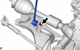
Remove the nut and separate the front stabilizer link assembly from the front stabilizer bar.
- NOTICE:
-
Do not damage the boot of the ball joint.
- HINT:
-
If the ball joint turns together with the nut, use a 6 mm hexagon socket wrench to hold the stud bolt.
48820B
2.SEPARATE FRONT STABILIZER LINK ASSEMBLY RH
- HINT:
-
Perform the same procedure as for the LH side.
3.REMOVE ENGINE ASSEMBLY WITH TRANSAXLE
for A25A-FKS:
Click hereEngine / Hybrid System>A25A-FKS (ENGINE MECHANICAL)>ENGINE ASSEMBLY>REMOVAL
for M20A-FKS:
Click hereEngine / Hybrid System>M20A-FKS (ENGINE MECHANICAL)>ENGINE ASSEMBLY>REMOVAL
for A25A-FXS:
Click hereEngine / Hybrid System>A25A-FXS (ENGINE MECHANICAL)>ENGINE ASSEMBLY>REMOVAL
48826
4.REMOVE FRONT STABILIZER BAR PROTECTOR (for Gasoline Model)
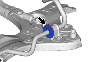
Remove the clip.
Remove the front stabilizer bar protector from the front stabilizer bar.
48829A
5.REMOVE FRONT NO. 1 STABILIZER BRACKET LH
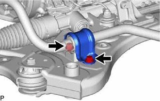
Remove the 2 bolts and front No. 1 stabilizer bracket LH from the front frame assembly.
48824A
6.REMOVE FRONT NO. 1 STABILIZER BRACKET RH
- HINT:
-
Perform the same procedure as for the LH side.
48811
7.REMOVE FRONT STABILIZER BAR
Remove the front stabilizer bar with 2 front stabilizer bar bushings from the front frame assembly.
48815
8.REMOVE FRONT NO. 1 STABILIZER BAR BUSHING (for LH Side)
Remove the front No. 1 stabilizer bar bushing from the front stabilizer bar.
48815
9.REMOVE FRONT NO. 1 STABILIZER BAR BUSHING (for RH Side)
- HINT:
-
Perform the same procedure as for the LH side.