M20A-FKS ENGINE CONTROL ACTIVE CONTROL ENGINE MOUNT(for Rear Side) REMOVAL
CAUTION / NOTICE / HINT
The necessary procedures (adjustment, calibration, initialization or registration) that must be performed after parts are removed and installed, or replaced during rear engine mounting insulator removal/installation are shown below.
| Replaced Part or Performed Procedure | Necessary Procedure | Effect/Inoperative Function when Necessary Procedure not Performed | Link |
|---|---|---|---|
|
*1: When performing learning using the GTS. Click here( *2: w/ Gasoline Particulate Filter |
|||
| Battery terminal is disconnected/reconnected | Drive the vehicle until stop and start control is permitted (approximately 5 to 60 minutes) | Stop and start system | ( ) |
| Perform steering sensor zero point calibration | Lane control system | ()
|
|
| Parking support brake system (for Gasoline model)*1 | |||
| Pre-collision system | |||
| Memorize steering angle neutral point | Parking assist monitor system | ()
|
|
| Panoramic view monitor system (for Gasoline model) | ()
|
||
| Reset back door close position | Power back door system (for Gasoline model) | ()
|
|
| Power back door initialization | Power door lock control system | ()
|
|
| Replacement of ECM | Perform Vehicle Identification Number (VIN) or frame number registration | DTC P063051 is output | ()
|
| ECU communication ID registration | Engine start function | See Service Bulletin for the registration method. | |
for M20A-FKS:
GPF Deposition Values*2 -
GPF deposition values save -
GPF deposition values write |
·
MIL comes on ·
Deterioration of fuel efficiency |
()
|
|
for K120:
·
Perform reset memory ·
Perform road test to allow TCM to learn |
·
Large shift shock ·
Deterioration of fuel efficiency |
()
|
|
for K120F:
·
Perform reset memory ·
Perform road test to allow TCM to learn |
·
Large shift shock ·
Deterioration of fuel efficiency |
()
|
|
| Gas leak from exhaust system is repaired | Inspection after repair | ·
Poor idle, etc. ·
Engine start function, etc. |
()
|
for M20A-FKS:
Front exhaust pipe assembly*2 |
GPF deposition value clear | ·
MIL comes on ·
Deterioration of fuel efficiency |
()
|
| Suspension, tires, etc. | ·
Ultrasonic sensor detection angle ·
Ultrasonic sensor detection angle registration |
Parking support brake system (for Gasoline model) | ()
|
| Television camera assembly optical axis (Back camera position setting) | Parking assist monitor system | ()
|
|
·
Parking assist ECU initialization ·
Adjust steering angle |
Panoramic view monitor system (for Gasoline model) | ()
|
|
| Front wheel alignment adjustment | 1.
Perform reset memory 2.
Perform acceleration sensor zero point calibration and store system information memorization. |
·
VSC is disabled or malfunctions ·
DTCs are output ·
Slip indicator light illuminates ·
ABS warning light illuminates |
()
|
| Front bumper assembly (Including removal and installation) | ·
Ultrasonic sensor detection angle ·
Ultrasonic sensor detection angle registration |
Parking support brake system (for Gasoline model) | ()
|
| Front television camera view adjustment | Panoramic view monitor system (for Gasoline model) | ()
|
|
- NOTICE:
-
After the ignition switch is turned off, the navigation system requires approximately a minute to record various types of memory and settings. As a result, after turning the ignition switch off, wait a minute or more before disconnecting the cable from the negative (-) battery terminal.
PROCEDURE

 51100G
1.REMOVE FRONT FRAME ASSEMBLY
12371A
2.REMOVE REAR ENGINE MOUNTING INSULATOR
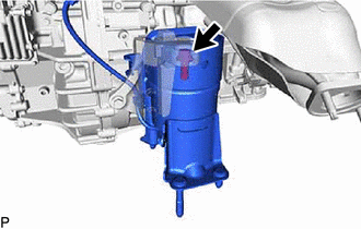
Remove the bolt and rear engine mounting insulator from the rear engine mounting bracket.
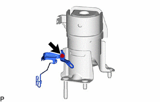
Remove the bolt and wire harness clamp bracket from the rear engine mounting insulator.
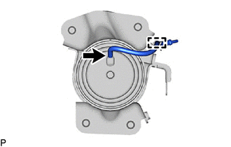
Detach the clamp and remove the vacuum hose from the rear engine mounting insulator.