LIGHTING (EXT) LIGHTING SYSTEM High Beam Headlight Circuit
DESCRIPTION
The headlight ECU sub-assembly controls the high beam headlights.
WIRING DIAGRAM
for Triple Beam Headlight
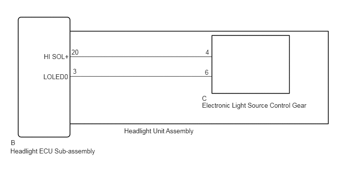
for Single Beam Headlight
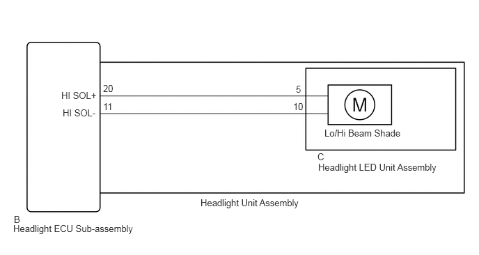
CAUTION / NOTICE / HINT
- NOTICE:
-
If the headlight ECU sub-assembly LH has been replaced, it is necessary to synchronize the vehicle information and initialize the headlight ECU sub-assembly LH.
-
Click hereVehicle Exterior>LIGHTING (EXT)>LIGHTING SYSTEM>INITIALIZATION
PROCEDURE
Check the illumination of each high beam lights.
- Result:
Result Proceed to LH side high beam light does not illuminate A RH side high beam light does not illuminate B
A
B
Connect the GTS to the DLC3.
Turn the ignition switch to ON.
Turn the GTS on.
Enter the following menus: Body Electrical / HL AutoLeveling / Active Test.
Perform the Active Test according to the display on the GTS.
- Body Electrical > HL AutoLeveling > Active Test
-
Tester Display Measurement Item Control Range Diagnostic Note Headlight High Beam High beam headlights OFF or ON -
- Body Electrical > HL AutoLeveling > Active Test
-
Tester Display Headlight High Beam - 50004 361 19
- OK:
High beam headlights turn on.
- Result:
Proceed to OK NG
OK
NG
Interchange the headlight unit assembly LH with RH and connect the connectors.
for Triple Beam Headlight:
Click hereVehicle Exterior>LIGHTING (EXT)>HEADLIGHT ASSEMBLY (for Triple Beam Headlight)>DISASSEMBLY
for Single Beam Headlight:
Click hereVehicle Exterior>LIGHTING (EXT)>HEADLIGHT ASSEMBLY(for Single Beam Headlight)>DISASSEMBLY
- Result:
Proceed to NEXT
NEXT
Check that the high beam headlight operates normally.
- OK:
High beam headlight operates normally.
- Result:
Proceed to OK NG (for Triple Beam Headlight) NG (for Single Beam Headlight)
OK
NG (for Triple Beam Headlight)
Click hereVehicle Exterior>LIGHTING (EXT)>HEADLIGHT ASSEMBLY (for Triple Beam Headlight)>DISASSEMBLY
NG (for Single Beam Headlight)
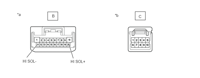
| *a | Component without harness connected
(to Headlight ECU Sub-assembly LH) |
*b | Component without harness connected
(to Headlight LED Unit Assembly LH) |
Remove the headlight assembly LH.
Click hereVehicle Exterior>LIGHTING (EXT)>HEADLIGHT ASSEMBLY(for Single Beam Headlight)>REMOVAL
Remove the headlight LED unit assembly LH.
Click hereVehicle Exterior>LIGHTING (EXT)>HEADLIGHT ASSEMBLY(for Single Beam Headlight)>DISASSEMBLY
Measure the resistance according to the value(s) in the table below.
- Standard Resistance:
Tester Connection Wiring Color Condition Specified Condition B-20 (HI SOL+) - C-5 R Always Below 1 Ω B-11 (HI SOL-) - C-10 B Always Below 1 Ω
- Result:
Proceed to OK NG
OK
NG
Connect the GTS to the DLC3.
Turn the ignition switch to ON.
Turn the GTS on.
Enter the following menus: Body Electrical / HL AutoLeveling (Sub) / Active Test.
Perform the Active Test according to the display on the GTS.
- Body Electrical > HL AutoLeveling (Sub) > Active Test
-
Tester Display Measurement Item Control Range Diagnostic Note Headlight High Beam High beam headlights OFF or ON -
- Body Electrical > HL AutoLeveling (Sub) > Active Test
-
Tester Display Headlight High Beam - 50004 414 4
- OK:
High beam headlights turn on.
- Result:
Proceed to OK NG
OK
NG
Interchange the headlight unit assembly RH with LH and connect the connectors.
for Triple Beam Headlight:
Click hereVehicle Exterior>LIGHTING (EXT)>HEADLIGHT ASSEMBLY (for Triple Beam Headlight)>DISASSEMBLY
for Single Beam Headlight:
Click hereVehicle Exterior>LIGHTING (EXT)>HEADLIGHT ASSEMBLY(for Single Beam Headlight)>DISASSEMBLY
- Result:
Proceed to NEXT
NEXT
Check that the high beam headlight operates normally.
- OK:
High beam headlight operates normally.
- Result:
Proceed to OK NG (for Triple Beam Headlight) NG (for Single Beam Headlight)
OK
NG (for Triple Beam Headlight)
Click hereVehicle Exterior>LIGHTING (EXT)>HEADLIGHT ASSEMBLY (for Triple Beam Headlight)>DISASSEMBLY
NG (for Single Beam Headlight)
| *a | Component without harness connected
(to Headlight ECU Sub-assembly RH) |
*b | Component without harness connected
(to Headlight LED Unit Assembly RH) |
Remove the headlight assembly RH.
Click hereVehicle Exterior>LIGHTING (EXT)>HEADLIGHT ASSEMBLY(for Single Beam Headlight)>REMOVAL
Remove the headlight LED unit assembly RH.
Click hereVehicle Exterior>LIGHTING (EXT)>HEADLIGHT ASSEMBLY(for Single Beam Headlight)>DISASSEMBLY
Measure the resistance according to the value(s) in the table below.
- Standard Resistance:
Tester Connection Wiring Color Condition Specified Condition B-20 (HI SOL+) - C-5 R Always Below 1 Ω B-11 (HI SOL-) - C-10 B Always Below 1 Ω
- Result:
Proceed to OK NG
OK
NG