SUPPLEMENTAL RESTRAINT SYSTEMS CURTAIN SHIELD AIRBAG ASSEMBLY INSTALLATION
CAUTION / NOTICE / HINT
- HINT:
- ·
Use the same procedure for RHD and LHD vehicles.
·The procedure listed below is for LHD vehicles.
·Use the same procedure for the RH and LH sides.
·The procedure listed below is for the LH side.
PROCEDURE

 62180A
1.INSTALL CURTAIN SHIELD AIRBAG ASSEMBLY LH (except Rollover Type)
When reusing the curtain shield airbag assembly LH:
- CAUTION:
-
Do not reuse the clip, roof side inner garnish clip and curtain shield airbag clip spacer.
Attach the claw to install new clip and new curtain shield airbag clip spacer to the front side of the curtain shield airbag assembly LH.
- NOTICE:
-
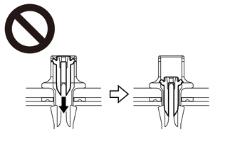
-
Do not push the pin and lock the clip at this time.
Attach the claw to install 2 new clips and new roof side inner garnish clip.
- NOTICE:
-
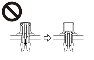
-
Do not push the pin and lock the clip at this time.
- HINT:
-
The roof side inner garnish clip is longer than the clip.
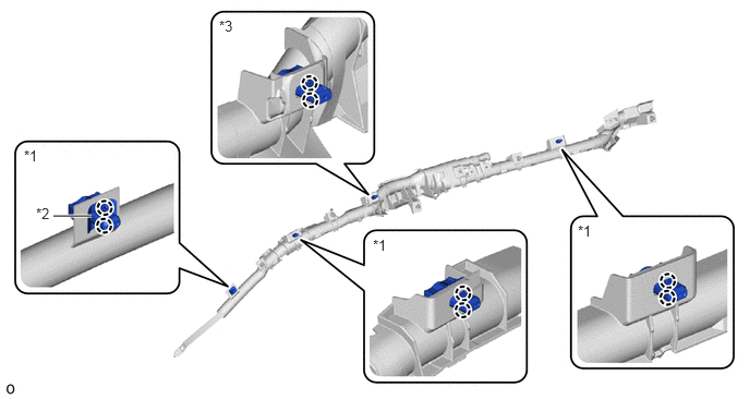
| *1 | Clip | *2 | Curtain Shield Airbag Clip Spacer |
| *3 | Roof Side Inner Garnish Clip | - | - |
Check that the ignition switch is off.
Check that the cable is disconnected from the negative (-) auxiliary battery terminal.
- CAUTION:
-
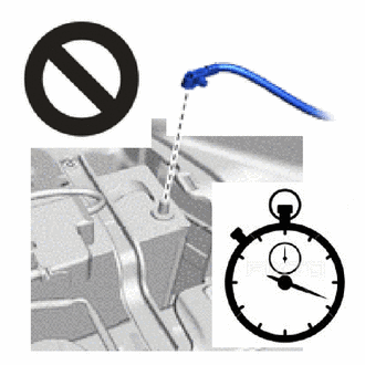
- ·
Do not begin this procedure within 90 seconds after disconnecting the cable from the negative (-) auxiliary battery terminal.
·If the airbag deploys for any reason, it may cause a serious accident.
Install the curtain shield airbag assembly LH inflator in the following order.
Attach the hook to set the curtain shield airbag assembly LH inflator.
Temporarily install the 2 new bolts.
Pull up and temporarily install the rear side of the curtain shield airbag assembly LH deployment portion with a new bolt.
Attach the hook and temporarily install the curtain shield airbag assembly LH strap with a new bolt.
Pull down the curtain shield airbag assembly LH deployment portion and tighten the 4 bolts in the order shown in the illustration.
- Torque:
- 9.8 N*m (100 kgf*cm, 87 in.*lbf)
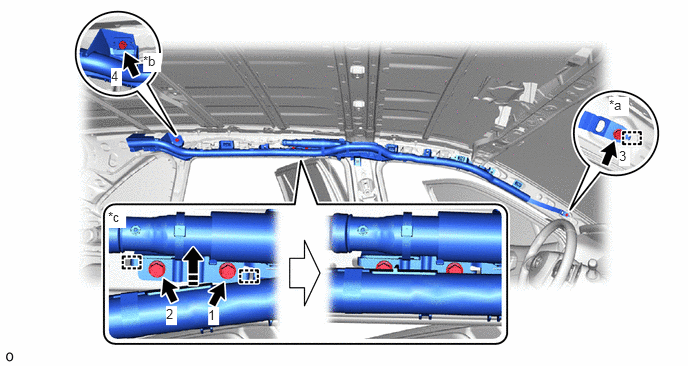
| *a | Strap | *b | Rear Side Bolt |
| *c | Curtain Shield Airbag Assembly LH Inflator | - | - |

|
Pull Up in this Direction | - | - |
Install the curtain shield airbag assembly LH deployment portion in the following order.
Attach the claw.
Attach the claw to install the curtain shield airbag assembly LH deployment portion with the 3 clips A and roof side inner garnish clip.
- NOTICE:
-
-
Do not push the pin and lock the clip at this time.
Check that there is no twisting in the curtain shield airbag assembly LH deployment portion.
Push the 4 pins to lock the 3 clips and roof side inner garnish clip.
- CAUTION:
-
Make sure that the pins of the clips are pushed in firmly.
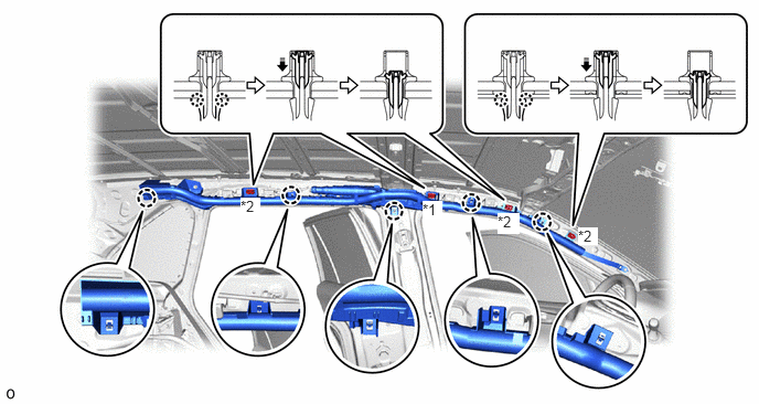
| *1 | Roof Side Inner Garnish Clip | *2 | Clip |
|
|
Push in this Direction | - | - |
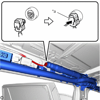
| *a | Lock Button |
|
|
Push in this Direction |
Connect the airbag connector and push the lock button to lock.
- NOTICE:
- ·
When connecting any airbag connector, take care not to damage the airbag wire harness.
·Make sure the lock button is securely locked.
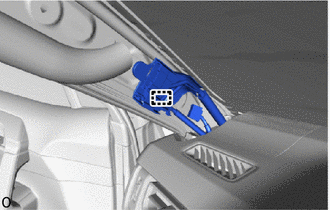
for LH Side:
Attach the wire harness clamp.
62180A
2.INSTALL CURTAIN SHIELD AIRBAG ASSEMBLY LH (for Rollover Type)
When reusing the curtain shield airbag assembly LH:
- CAUTION:
-
Do not reuse the clip A, clip B, roof side inner garnish clip and curtain shield airbag clip spacer.
Attach the claw to install 2 new clips A and new roof side inner garnish clip.
- NOTICE:
-
-
Do not push the pin and lock the clip at this time.
- HINT:
-
The roof side inner garnish clip is longer than the clip A.
Attach the claw to install new clip A and new curtain shield airbag clip spacer to the front side of the curtain shield airbag assembly LH.
- NOTICE:
-
-
Do not push the pin and lock the clip at this time.
Install 2 new clips B.
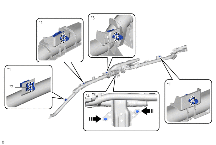
| *1 | Clip A | *2 | Curtain Shield Airbag Clip Spacer |
| *3 | Roof Side Inner Garnish Clip | *4 | Clip B |
|
|
Install in this Direction | - | - |
Check that the ignition switch is off.
Check that the cable is disconnected from the negative (-) auxiliary battery terminal.
- CAUTION:
-
- ·
Do not begin this procedure within 90 seconds after disconnecting the cable from the negative (-) auxiliary battery terminal.
·If the airbag deploys for any reason, it may cause a serious accident.
Install the curtain shield airbag assembly LH inflator in the following order.
Temporarily install the curtain shield airbag assembly LH inflator with 2 new bolts A.
Attach the clip B to temporarily install the bracket.
Temporarily install the 4 new bolts B to the bracket.
Pull up and temporarily install the rear side of the curtain shield airbag assembly LH deployment portion with a new bolt A.
Attach the hook and temporarily install the curtain shield airbag assembly LH strap with a new bolt A.
Pull down the curtain shield airbag assembly LH deployment portion and tighten the 2 bolts A in the order shown in the illustration (1 → 2 in illustration).
- Torque:
- for Bolt A:
9.8 N*m (100 kgf*cm, 87 in.*lbf)
Tighten the 2 bolts A and 4 bolts B in the order shown in the illustration (3 → 8 in illustration).
- Torque:
- for Bolt A:
9.8 N*m (100 kgf*cm, 87 in.*lbf)
- for Bolt B:
6.0 N*m (61 kgf*cm, 53 in.*lbf)
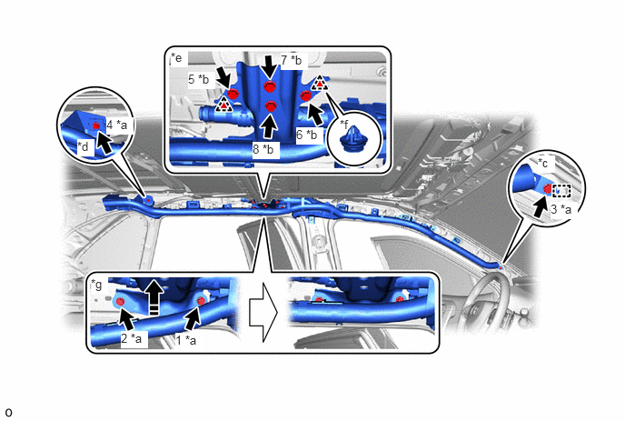
| *a | Bolt A | *b | Bolt B |
| *c | Strap | *d | Rear Side Bolt |
| *e | Bracket | *f | Clip B |
| *g | Curtain Shield Airbag Assembly LH Inflator | - | - |
|
|
Pull Up in this Direction | - | - |
Install the curtain shield airbag assembly LH deployment portion in the following order.
Attach the claw.
Attach the claw to install the curtain shield airbag assembly LH deployment portion with the 3 clips A and roof side inner garnish clip.
- NOTICE:
-
-
Do not push the pin and lock the clip at this time.
Check that there is no twisting in the curtain shield airbag assembly LH deployment portion.
Push the 4 pins to lock the 3 clips A and roof side inner garnish clip.
- CAUTION:
-
Make sure that the pins of the clips are pushed in firmly.
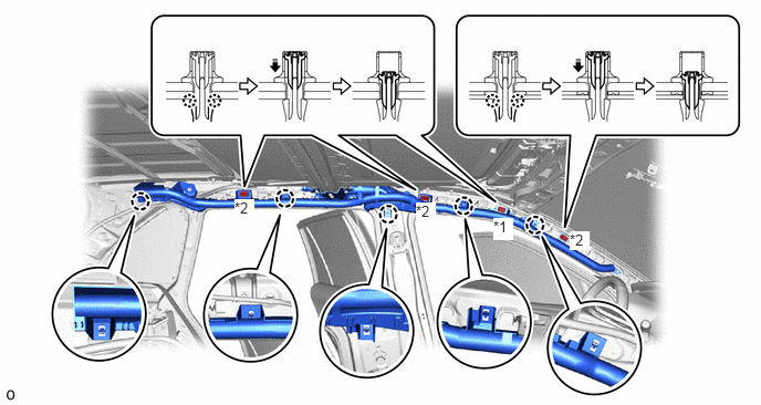
| *1 | Roof Side Inner Garnish Clip | *2 | Clip A |
|
|
Push in this Direction | - | - |
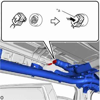
| *a | Lock Button |
|
|
Push in this Direction |
Connect the airbag connector and push the lock button to lock.
- NOTICE:
- ·
When connecting any airbag connector, take care not to damage the airbag wire harness.
·Make sure the lock button is securely locked.
for LH Side:
Attach the wire harness clamp.
3.INSTALL ROOF HEADLINING ASSEMBLY
4.CONNECT CABLE TO NEGATIVE AUXILIARY BATTERY TERMINAL
for A25A-FKS:
for M20A-FKS:
for A25A-FXS:
Click hereGeneral>MAINTENANCE>A25A-FXS AUXILIARY BATTERY>INSTALLATION
for A25B-FXS:
Click hereGeneral>MAINTENANCE>A25B-FXS AUXILIARY BATTERY>INSTALLATION
- NOTICE:
-
When disconnecting the cable, some systems need to be initialized after the cable is reconnected.
-
Click hereGeneral>INTRODUCTION>REPAIR INSTRUCTION>INITIALIZATION
65351A
5.INSTALL BATTERY HOLE COVER (for HV Model)
58416K
6.INSTALL REAR NO. 2 FLOOR BOARD (for HV Model)
58410B
7.INSTALL DECK BOARD ASSEMBLY (for HV Model)
8. PERFORM DIAGNOSTIC SYSTEM CHECK
w/o Occupant Classification System:
for Gasoline Model with Occupant Classification System:
for HV Model with Occupant Classification System:
9.CHECK SRS WARNING LIGHT
w/o Occupant Classification System:
for Gasoline Model with Occupant Classification System:
for HV Model with Occupant Classification System:
10.PERFORM SYSTEM INITIALIZATION AND CALIBRATION