EXTERIOR PANELS / TRIM REAR BUMPER INSTALLATION
PROCEDURE

 52023
1.INSTALL REAR BUMPER REINFORCEMENT SUB-ASSEMBLY
for Type A:
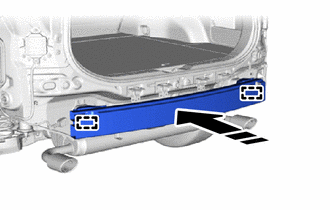

|
Install in this Direction |
Attach the guide to set the rear bumper reinforcement sub-assembly.
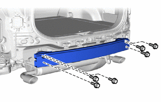
Install the rear bumper reinforcement sub-assembly with the 6 bolts.
- Torque:
- 29 N*m (296 kgf*cm, 21 ft.*lbf)
for Type B:
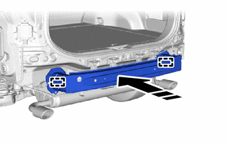
|
|
Install in this Direction |
Attach the guide to set the rear bumper reinforcement sub-assembly.
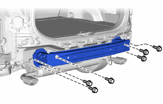
Install the rear bumper reinforcement sub-assembly with the 6 bolts.
- Torque:
- 29 N*m (296 kgf*cm, 21 ft.*lbf)
52156A
2.INSTALL REAR BUMPER SIDE SUPPORT LH
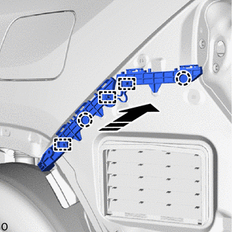
|
|
Install in this Direction |
Attach the guide and claw to install the rear bumper side support LH.
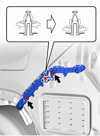
Install the clip.
Install the 2 screws.
52155A
3.INSTALL REAR BUMPER SIDE SUPPORT RH
- HINT:
-
Use the same procedure for the RH and LH side.
52563A
4.INSTALL REAR BUMPER UPPER RETAINER LH
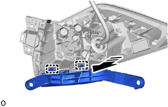
|
|
Install in this Direction |
Attach the guide to install the rear bumper upper retainer LH to the rear combination light assembly LH.
52562B
5.INSTALL REAR BUMPER UPPER RETAINER RH
- HINT:
-
Use the same procedure for the RH and LH side.
6.INSTALL REAR COMBINATION LIGHT ASSEMBLY LH
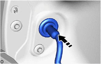
|
|
Install in this Direction |
Pass the wire harness into the vehicle and install the grommet.
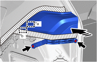
| *a | Pin |
| *b | Guide |
|
|
Push in this Direction |
Align the guide and pin to set the rear combination light assembly LH.
Push the rear combination light assembly LH towards the vehicle front to attach the pin and guide.
Install the 2 screws.
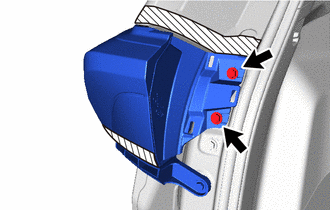
Install the 2 screws.
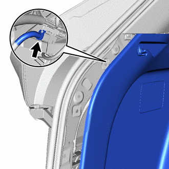
Insert your hand between the deck trim side panel assembly LH and the body and connect the connector.
7.INSTALL REAR COMBINATION LIGHT ASSEMBLY RH
- HINT:
-
Use the same procedure for the RH and LH side.
8.INSTALL DECK TRIM SIDE PANEL ASSEMBLY LH
Return the rear side of the deck trim side panel assembly LH to its original position.
Click hereVehicle Interior>INTERIOR PANELS / TRIM>ROOF HEADLINING>INSTALLATION
9.INSTALL DECK TRIM SIDE PANEL ASSEMBLY RH
- HINT:
-
Use the same procedure for the RH and LH side.
58460D
10.INSTALL LUGGAGE HOLD BELT STRIKER ASSEMBLY
58386
11.INSTALL REAR FLOOR FINISH PLATE
58417H
12.INSTALL REAR NO. 3 FLOOR BOARD
13.INSTALL REAR BUMPER ASSEMBLY
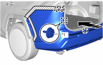
| *1 | Back Door Garnish Retainer |
|
|
Install in this Direction |
Attach the claw and back door garnish retainer to set the rear bumper assembly.
- HINT:
-
Use the same procedure for the RH and LH side.
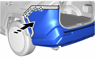
|
|
Install in this Direction |
Attach the claw.
- HINT:
-
Use the same procedure for the RH and LH side.
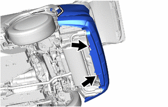
Install the 2 clips.
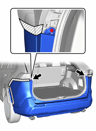
Install the 2 screws.
Remove the protective tape.
except Off Road Package:
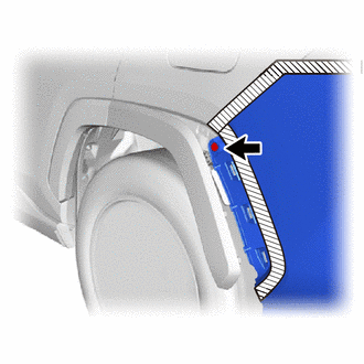
Install the clip.
- HINT:
-
Use the same procedure for the RH and LH side.
for Off Road Package:
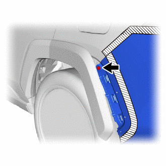
Install the clip.
- HINT:
-
Use the same procedure for the RH and LH side.
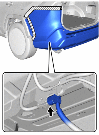
w/ TOYOTA Parking Assist-sensor System, w/ Hands Free Power Back Door:
Connect the connector.
52599
14.INSTALL REAR BUMPER UPPER STOPPER
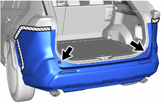
Install the 2 rear bumper upper stoppers.
81498
15.INSTALL REAR COMBINATION LIGHT COVER LH
81497
16.INSTALL REAR COMBINATION LIGHT COVER RH
- HINT:
-
Use the same procedure for the RH and LH side.
75606A
17.INSTALL QUARTER OUTSIDE MOULDING SUB-ASSEMBLY LH
except Off Road Package:
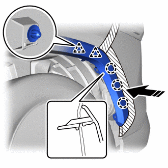
|
|
Install in this Direction |
Attach the claw and clip to install the quarter outside moulding sub-assembly LH.
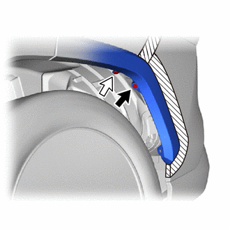

|
Screw |

|
Clip |
Install the screw.
Install the clip.
Remove the protective tape.
for Off Road Package:
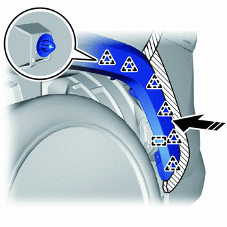
|
|
Install in this Direction |
Attach the guide and clip to install the quarter outside moulding sub-assembly LH.
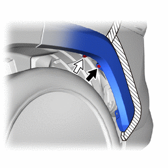
|
|
Screw |
|
|
Clip |
Install the screw.
Install the clip.
Remove the protective tape.
75605A
18.INSTALL QUARTER OUTSIDE MOULDING SUB-ASSEMBLY RH
- HINT:
-
Use the same procedure for the RH and LH side.
52592
19.INSTALL REAR BUMPER SIDE SEAL LH
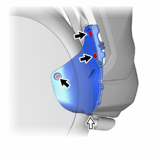
|
|
Clip |
|
|
Screw |
w/o Mudguard:
Install the rear bumper side seal LH with the 3 clips.
Install the screw.
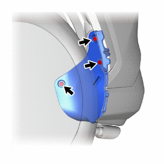
w/ Mudguard:
Install the rear bumper side seal LH with the 3 clips.
52591
20.INSTALL REAR BUMPER SIDE SEAL RH
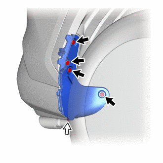
|
|
Clip |
|
|
Screw |
w/o Mudguard:
Install the rear bumper side seal RH with the 4 clips.
Install the screw.
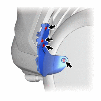
w/ Mudguard:
Install the rear bumper side seal RH with the 4 clips.
76626E
21.INSTALL REAR QUARTER PANEL MUDGUARD LH (w/ Mudguard)
76625G
22.INSTALL REAR QUARTER PANEL MUDGUARD RH (w/ Mudguard)
- HINT:
-
Use the same procedure for the RH and LH side.
23.CONNECT CABLE TO NEGATIVE AUXILIARY BATTERY TERMINAL (w/ Hands Free Power Back Door)
for A25A-FXS:
Click hereGeneral>MAINTENANCE>A25A-FXS AUXILIARY BATTERY>INSTALLATION
for A25A-FKS:
for M20A-FKS:
for A25B-FXS:
Click hereGeneral>MAINTENANCE>A25B-FXS AUXILIARY BATTERY>INSTALLATION
- NOTICE:
-
When disconnecting the cable, some systems need to be initialized after the cable is reconnected.
-
Click hereGeneral>INTRODUCTION>REPAIR INSTRUCTION>INITIALIZATION
65351A
24.INSTALL BATTERY HOLE COVER (for HV Model)
for A25A-FXS:
Click hereGeneral>MAINTENANCE>A25A-FXS AUXILIARY BATTERY>INSTALLATION
for A25B-FXS:
Click hereGeneral>MAINTENANCE>A25B-FXS AUXILIARY BATTERY>INSTALLATION
58416K
25.INSTALL REAR NO. 2 FLOOR BOARD (for HV Model)
for A25A-FXS:
Click hereGeneral>MAINTENANCE>A25A-FXS AUXILIARY BATTERY>INSTALLATION
for A25B-FXS:
Click hereGeneral>MAINTENANCE>A25B-FXS AUXILIARY BATTERY>INSTALLATION
58410B
26.INSTALL DECK BOARD ASSEMBLY (for HV Model)
for A25A-FXS:
Click hereGeneral>MAINTENANCE>A25A-FXS AUXILIARY BATTERY>INSTALLATION
for A25B-FXS:
Click hereGeneral>MAINTENANCE>A25B-FXS AUXILIARY BATTERY>INSTALLATION
891B2
27.CHECK KICK DOOR CONTROL SENSOR (w/ Hands Free Power Back Door)
for HV Model:
Click hereVehicle Exterior>DOOR / HATCH>POWER BACK DOOR SYSTEM (for HV Model)>DATA LIST / ACTIVE TEST
for Gasoline Model:
Click hereVehicle Exterior>DOOR / HATCH>POWER BACK DOOR SYSTEM (for Gasoline Model)>DATA LIST / ACTIVE TEST
28.PERFORM CALIBRATION (w/ Parking Support Brake System)
for Gasoline Model: