REAR SUSPENSION REAR UPPER ARM REMOVAL
CAUTION / NOTICE / HINT
The necessary procedures (adjustment, calibration, initialization, or registration) that must be performed after parts are removed and installed, or replaced during rear upper control arm assembly removal/installation are shown below.
| Replaced Part or Performed Procedure | Necessary Procedure | Effect/Inoperative Function when Necessary Procedure not Performed | Link |
|---|---|---|---|
|
*: When performing learning using the GTS. Click here( |
|||
| Auxiliary battery terminal is disconnected/reconnected | Perform steering sensor zero point calibration | Lane control system | ( ) |
| Parking support brake system (for HV model)* | |||
| Pre-collision system | |||
| Memorize steering angle neutral point | Parking assist monitor system | ()
|
|
| Panoramic view monitor system (for HV model) | ()
|
||
| Reset back door close position | Power back door system (for HV model) | ()
|
|
| Power back door initialization | Power door lock control system | ()
|
|
| Rear wheel alignment adjustment | 1.
Clear zero point calibration data. 2.
Perform yaw rate and acceleration sensor zero point calibration. |
·
DTCs are stored ·
ABS warning light illuminates ·
Brake warning light / yellow (minor malfunction) illuminates ·
Slip indicator light illuminates ·
VSC disabled or malfunctions |
()
|
| Suspension, tires, etc.
(The vehicle height changes because of suspension or tire replacement.) |
·
Ultrasonic sensor detection angle ·
Ultrasonic sensor detection angle registration |
Parking Support Brake System (for HV model) | ()
|
| Television camera assembly optical axis (Back camera position setting) | Parking Assist Monitor System | ()
|
|
·
Parking assist ECU initialization ·
Adjust steering angle |
Panoramic View Monitor System (for HV model) | ()
|
|
| Perform headlight ECU sub-assembly LH initialization | Lighting System (EXT) | ()
|
|
| Gas leak from exhaust system is repaired | Inspection After Repair | ·
Poor idle, etc. ·
Engine start function, etc. |
·
for A25A-FXS w/ Canister Pump Module: ( ·
for A25A-FXS w/o Canister Pump Module: ( ·
for A25B-FXS: ( |
| Replaced Part or Performed Procedure | Necessary Procedure | Effect/Inoperative Function when Necessary Procedure not Performed | Link |
|---|---|---|---|
| Rear wheel alignment adjustment | ·
Perform reset memory ·
Perform acceleration sensor zero point calibration and store system information memorization. |
·
VSC is disabled or malfunctions ·
DTCs are output ·
Slip indicator light illuminates ·
ABS warning light illuminates |
()
|
| Suspension, tires, etc.
(The vehicle height changes because of suspension or tire replacement.) |
·
Ultrasonic sensor detection angle ·
Ultrasonic sensor detection angle registration |
Parking Support Brake System (for Gasoline model) | ()
|
| Television camera assembly optical axis (Back camera position setting) | Parking Assist Monitor System | ()
|
|
·
Parking assist ECU initialization ·
Adjust steering angle |
Panoramic View Monitor System (for Gasoline model) | ()
|
|
| Perform headlight ECU sub-assembly LH initialization | Lighting System (EXT) | ()
|
|
| Gas leak from exhaust system is repaired | Inspection After Repair | ·
Poor idle, etc. ·
Engine start function, etc. |
·
for A25A-FKS w/ Canister Pump Module: ( ·
for A25A-FKS w/o Canister Pump Module: ( ·
for M20A-FKS: ( |
- CAUTION:
- ·
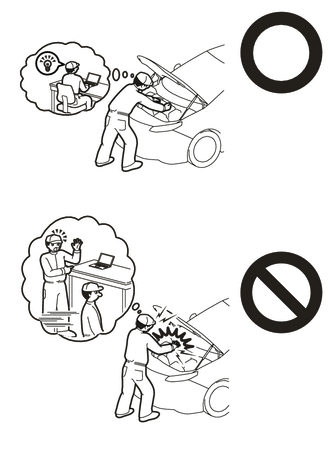
This vehicle has contains high voltage circuits standardized with orange colored wiring and connectors, so follow the instructions in this manual to perform the procedures correctly.
·If the correct procedures are not followed according to the instructions in this manual, there is a danger of electric shock from the high voltage circuits.
·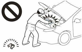
Be sure to wear insulating gloves when working on high voltage wiring or components.
·If work is performed without wearing insulating gloves, there is a danger of electric shock.
·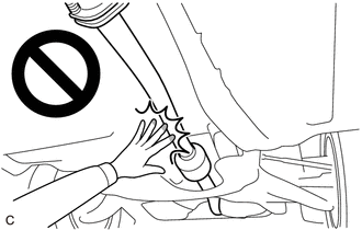
To prevent burns, do not touch the engine, exhaust pipe or other high temperature components while the engine is hot.
- NOTICE:
-
After the ignition switch is turned off, the navigation system requires approximately a minute to record various types of memory and settings. As a result, after turning the ignition switch off, wait a minute or more before disconnecting the cable from the negative (-) battery terminal.
PROCEDURE

 51206A
1.REMOVE REAR SUSPENSION MEMBER SUB-ASSEMBLY
for 2WD:
Click hereSuspension>REAR SUSPENSION>REAR SUSPENSION MEMBER (for 2WD)>REMOVAL
for HV Model 4WD/AWD
Click hereSuspension>REAR SUSPENSION>REAR SUSPENSION MEMBER (for HV Model 4WD/AWD)>REMOVAL
for Gasoline Model 4WD/AWD
Click hereSuspension>REAR SUSPENSION>REAR SUSPENSION MEMBER (for Gasoline Model 4WD/AWD)>REMOVAL
48790
2.REMOVE REAR UPPER CONTROL ARM ASSEMBLY LH
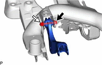
Remove the bolt, nut and rear upper control arm assembly LH from the rear suspension member sub-assembly.
- NOTICE:
-
Because the nut has its own stopper, do not turn the nut. Loosen the bolt with the nut secured.
48770A
3.REMOVE REAR UPPER CONTROL ARM ASSEMBLY RH
- HINT:
-
Perform the same procedure as for the LH side.