LIGHTING (INT) INTERIOR ILLUMINATION LIGHT(for Driver Side) REMOVAL
CAUTION / NOTICE / HINT
The necessary procedures (adjustment, calibration, initialization or registration) that must be performed after parts are removed, installed or replaced during the No. 1 interior illumination light assembly removal/installation are shown below.
| Replacement Part or Procedure | Necessary Procedures | Effect/Inoperative Function When Necessary Procedures not Performed | Link |
|---|---|---|---|
|
*: When performing learning using the GTS. Click here( |
|||
| Disconnect cable from negative (-) auxiliary battery terminal | Drive the vehicle until stop and start control is permitted (approximately 5 to 60 minutes) | Stop and start system | for A25A-FKS:( ) for M20A-FKS:( )
|
| Perform steering sensor zero point calibration | Lane control system | ()
|
|
| Parking support brake system (for Gasoline model)* | |||
| Pre-collision system | |||
| Memorize steering angle neutral point | Parking assist monitor system | ()
|
|
| Panoramic view monitor system (for Gasoline model) | ()
|
||
| Reset back door close position | Power back door system (for Gasoline model) | ()
|
|
| Power back door initialization | Power door lock control system | ()
|
|
- NOTICE:
-
After the ignition switch is turned off, the navigation system requires approximately a minute to record various types of memory and settings. As a result, after turning the ignition switch off, wait a minute or more before disconnecting the cable from the negative (-) auxiliary battery terminal.
| Replacement Part or Procedure | Necessary Procedures | Effect/Inoperative Function When Necessary Procedures not Performed | Link |
|---|---|---|---|
|
*: When performing learning using the GTS. Click here( |
|||
| Disconnect cable from negative (-) auxiliary battery terminal | Perform steering sensor zero point calibration | Lane control system | ()
|
| Parking support brake system (for HV model)* | |||
| Pre-collision system | |||
| Memorize steering angle neutral point | Parking assist monitor system | ()
|
|
| Panoramic view monitor system (for HV model) | ()
|
||
| Reset back door close position | Power back door system (for HV model) | ()
|
|
| Power back door initialization | Power door lock control system | ()
|
|
- NOTICE:
-
After the ignition switch is turned off, the navigation system requires approximately a minute to record various types of memory and settings. As a result, after turning the ignition switch off, wait a minute or more before disconnecting the cable from the negative (-) auxiliary battery terminal.
- HINT:
- ·
Use the same procedure for RHD and LHD vehicles.
·The procedure listed below is for LHD vehicles.
PROCEDURE

 1. PRECAUTION
- CAUTION:
-
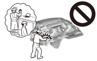
-
Be sure to read precaution thoroughly before servicing.
-
Click hereGeneral>INTRODUCTION>REPAIR INSTRUCTION>PRECAUTION
- NOTICE:
-
After turning the ignition switch off, waiting time may be required before disconnecting the cable from the negative (-) auxiliary battery terminal. Therefore, make sure to read the disconnecting the cable from the negative (-) auxiliary battery terminal notices before proceeding with work.
58410B
2.REMOVE DECK BOARD ASSEMBLY (for HV Model)
58416K
3.REMOVE REAR NO. 2 FLOOR BOARD (for HV Model)
65351A
4.REMOVE BATTERY HOLE COVER (for HV Model)
5.DISCONNECT CABLE FROM NEGATIVE AUXILIARY BATTERY TERMINAL
Disconnect the cable from the negative (-) auxiliary battery terminal.
for A25A-FKS:
for M20A-FKS:
for A25A-FXS:
Click hereGeneral>MAINTENANCE>A25A-FXS AUXILIARY BATTERY>REMOVAL
for A25B-FXS:
Click hereGeneral>MAINTENANCE>A25B-FXS AUXILIARY BATTERY>REMOVAL
- CAUTION:
-
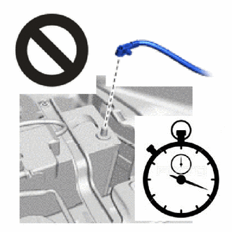
- ·
Wait at least 90 seconds after disconnecting the cable from the negative (-) auxiliary battery terminal to disable the SRS system.
·If the airbag deploys for any reason, it may cause a serious accident.
- NOTICE:
-
When disconnecting the cable, some systems need to be initialized after the cable is reconnected.
-
Click hereGeneral>INTRODUCTION>REPAIR INSTRUCTION>INITIALIZATION
6.REMOVE INSTRUMENT PANEL SAFETY PAD ASSEMBLY
81080J
7.REMOVE NO. 1 INTERIOR ILLUMINATION LIGHT ASSEMBLY
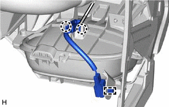

|
Protective Tape |
Detach the clamp.
Using a thin-bladed screwdriver, detach the claw and remove the No. 1 interior illumination light assembly.
- HINT:
-
Tape the thin-bladed screwdriver tip before use.
82285B
8.REMOVE ILLUMINATION WIRE
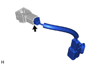
Disconnect the connector and remove the illumination wire.