EXTERIOR PANELS / TRIM REAR BUMPER REMOVAL
CAUTION / NOTICE / HINT
The necessary procedures (adjustment, calibration, initialization, or registration) that must be performed after parts are removed, installed, or replaced during the Rear bumper assembly removal/installation are shown below.
| Replaced Part or Performed Procedure | Necessary Procedure | Effect/Inoperative Function when Necessary Procedure not Performed | Link |
|---|---|---|---|
|
*: When performing learning using the GTS. Click here( |
|||
| Removal and installation of auxiliary battery terminal | Perform steering sensor zero point calibration | Lane control system | ( ) |
| Parking support brake system (for HV Model)* | |||
| Pre-collision system | |||
| Memorize steering angle neutral point | Parking assist monitor system | ()
|
|
| Panoramic view monitor system (for HV Model) | ()
|
||
| Reset back door close position | Power back door system (for HV Model) | ()
|
|
| Power back door initialization | Power door lock control system | ()
|
|
| Rear bumper assembly (Including removal and installation) | ·
Ultrasonic sensor detection angle ·
Ultrasonic sensor detection angle registration |
Parking support brake system (for HV Model) | ()
|
| Kick door control sensor | Reset connection history | There are cases where the connection history display differs from the vehicle condition | ()
|
- NOTICE:
-
After the ignition switch is turned off, the navigation system requires approximately a minute to record various types of memory and settings. As a result, after turning the ignition switch off, wait a minute or more before disconnecting the cable from the negative (-) auxiliary battery terminal.
| Replaced Part or Performed Procedure | Necessary Procedure | Effect/Inoperative Function when Necessary Procedure not Performed | Link |
|---|---|---|---|
|
*: When performing learning using the GTS. Click here( |
|||
| Removal and installation of auxiliary battery terminal | Drive the vehicle until stop and start control is permitted (approximately 5 to 60 minutes) | Stop and start system | for A25A-FKS:()
for M20A-FKS:( )
|
| Perform steering sensor zero point calibration | Lane control system | ()
|
|
| Parking support brake system (for Gasoline Model)* | |||
| Pre-collision system | |||
| Memorize steering angle neutral point | Parking assist monitor system | ()
|
|
| Panoramic view monitor system (for Gasoline Model) | ()
|
||
| Reset back door close position | Power back door system (for Gasoline Model) | ()
|
|
| Power back door initialization | Power door lock control system | ()
|
|
| Rear bumper assembly (Including removal and installation) | ·
Ultrasonic sensor detection angle ·
Ultrasonic sensor detection angle registration |
Parking support brake system (for Gasoline Model) | ()
|
| Kick door control sensor | Reset connection history | There are cases where the connection history display differs from the vehicle condition | ()
|
- NOTICE:
-
After the ignition switch is turned off, the navigation system requires approximately a minute to record various types of memory and settings. As a result, after turning the ignition switch off, wait a minute or more before disconnecting the cable from the negative (-) auxiliary battery terminal.
- HINT:
-
If the bumper is damaged, there is a possibility that the installation area of the blind spot monitor sensor may be deformed and the blind spot monitor system may not operate correctly, so visually inspect the blind spot monitor sensor installation area (frame, stud bolt) to make sure it is not dented or bent.
-
Click hereAudio / Visual / Telematics>PARK ASSIST / MONITORING>BLIND SPOT MONITOR SENSOR>ADJUSTMENT
-
If the visual inspection finds a problem, check the installation condition of the blind spot monitor sensor, and adjust the installation position of the blind spot monitor sensor as necessary.
PROCEDURE

 1. PRECAUTION
- NOTICE:
-
After turning the ignition switch off, waiting time may be required before disconnecting the cable from the negative (-) auxiliary battery terminal. Therefore, make sure to read the disconnecting the cable from the negative (-) auxiliary battery terminal notices before proceeding with work.
-
Click hereGeneral>INTRODUCTION>REPAIR INSTRUCTION>PRECAUTION
58410B
2.REMOVE DECK BOARD ASSEMBLY (for HV Model)
for A25A-FXS:
Click hereGeneral>MAINTENANCE>A25A-FXS AUXILIARY BATTERY>REMOVAL
for A25B-FXS:
Click hereGeneral>MAINTENANCE>A25B-FXS AUXILIARY BATTERY>REMOVAL
58416K
3.REMOVE REAR NO. 2 FLOOR BOARD (for HV Model)
for A25A-FXS:
Click hereGeneral>MAINTENANCE>A25A-FXS AUXILIARY BATTERY>REMOVAL
for A25B-FXS:
Click hereGeneral>MAINTENANCE>A25B-FXS AUXILIARY BATTERY>REMOVAL
65351A
4.REMOVE BATTERY HOLE COVER (for HV Model)
for A25A-FXS:
Click hereGeneral>MAINTENANCE>A25A-FXS AUXILIARY BATTERY>REMOVAL
for A25B-FXS:
Click hereGeneral>MAINTENANCE>A25B-FXS AUXILIARY BATTERY>REMOVAL
5.DISCONNECT CABLE FROM NEGATIVE AUXILIARY BATTERY TERMINAL (w/ Hands Free Power Back Door)
for A25A-FXS:
Click hereGeneral>MAINTENANCE>A25A-FXS AUXILIARY BATTERY>REMOVAL
for A25A-FKS:
for M20A-FKS:
for A25B-FXS:
Click hereGeneral>MAINTENANCE>A25B-FXS AUXILIARY BATTERY>REMOVAL
- NOTICE:
-
When disconnecting the cable, some systems need to be initialized after the cable is reconnected.
-
Click hereGeneral>INTRODUCTION>REPAIR INSTRUCTION>INITIALIZATION
76626E
6.REMOVE REAR QUARTER PANEL MUDGUARD LH (w/ Mudguard)
76625G
7.REMOVE REAR QUARTER PANEL MUDGUARD RH (w/ Mudguard)
- HINT:
-
Use the same procedure for the RH and LH side.
52592
8.REMOVE REAR BUMPER SIDE SEAL LH
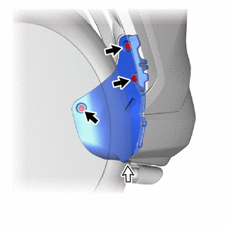

|
Clip |

|
Screw |
w/o Mudguard:
Remove the 3 clips.
Remove the screw and rear bumper side seal LH.
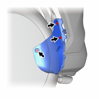
w/ Mudguard:
Remove the 3 clips and rear bumper side seal LH.
52591
9.REMOVE REAR BUMPER SIDE SEAL RH
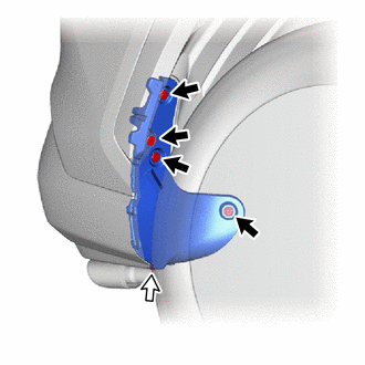
|
|
Clip |
|
|
Screw |
w/o Mudguard:
Remove the 4 clips.
Remove the screw and rear bumper side seal RH.
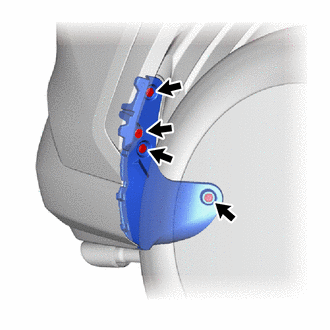
w/ Mudguard:
Remove the 4 clips and rear bumper side seal RH.
75606A
10.REMOVE QUARTER OUTSIDE MOULDING SUB-ASSEMBLY LH
except Off Road Package:
Apply protective tape around the quarter outside moulding sub-assembly LH.
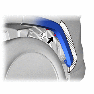
|
|
Screw |
|
|
Clip |
Remove the screw.
Remove the clip.
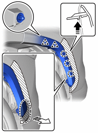

|
Place Hand Here |

|
Remove in this Direction (1) |

|
Remove in this Direction (2) |
Pull back the edge of the rear wheel house liner LH and detach the claw.
- NOTICE:
- ·
Do not apply excessive force when pulling back the rear wheel house liner LH.
·To avoid damaging the claw, do not forcibly pull the rear quarter outside moulding sub-assembly LH.
Detach the clip and disconnect the rear quarter outside moulding sub-assembly LH.
for Off Road Package:
Apply protective tape around the quarter outside moulding sub-assembly LH.
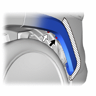
|
|
Screw |
|
|
Clip |
Remove the screw.
Remove the clip.
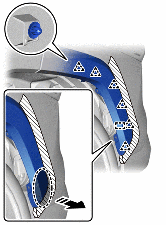
|
|
Place Hand Here |
|
|
Remove in this Direction |
Pull back the edge of the rear wheel house liner LH and detach the clip and guide.
- NOTICE:
- ·
Do not apply excessive force when pulling back the rear wheel house liner LH.
·To avoid damaging the clip, do not forcibly pull the rear quarter outside moulding sub-assembly LH.
Disconnect the rear quarter outside moulding sub-assembly LH.
75605A
11.REMOVE QUARTER OUTSIDE MOULDING SUB-ASSEMBLY RH
- HINT:
-
Use the same procedure for the RH and LH side.
81498
12.REMOVE REAR COMBINATION LIGHT COVER LH
81497
13.REMOVE REAR COMBINATION LIGHT COVER RH
- HINT:
-
Use the same procedure for the RH and LH side.
52599
14.REMOVE REAR BUMPER UPPER STOPPER
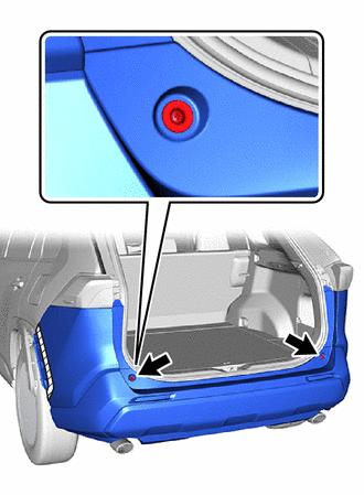
Remove the 2 rear bumper upper stoppers.
15.REMOVE REAR BUMPER ASSEMBLY
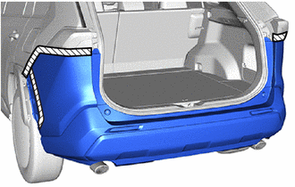

|
Protective Tape |
Apply protective tape around the rear bumper assembly.
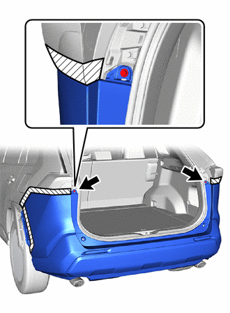
Remove the 2 screws.
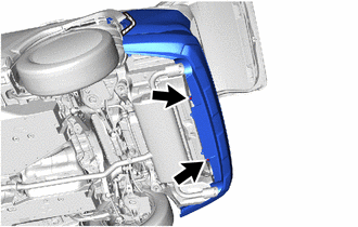
Remove the 2 clips.
except Off Road Package:
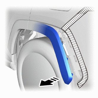
|
|
Remove in this Direction |
Pull the rear quarter outside moulding sub-assembly LH toward the outside as shown in the illustration.
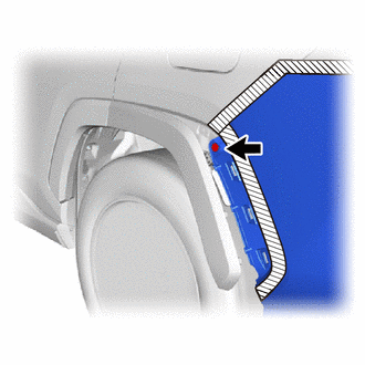
Remove the clip.
- HINT:
-
Use the same procedure for the RH and LH side.
for Off Road Package:
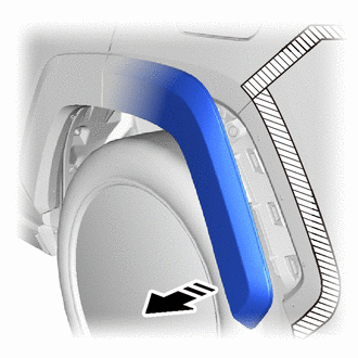
|
|
Remove in this Direction |
Pull the rear quarter outside moulding sub-assembly LH toward the outside as shown in the illustration.
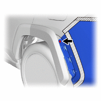
Remove the clip.
- HINT:
-
Use the same procedure for the RH and LH side.
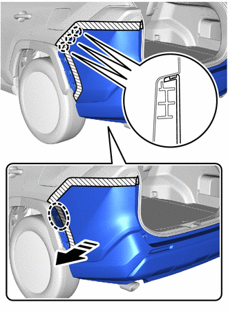
|
|
Place Hand Here |
|
|
Remove in this Direction |
Detach the claw as shown in the illustration.
- HINT:
-
Use the same procedure for the RH and LH side.
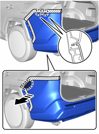
|
|
Place Hand Here |
|
|
Remove in this Direction |
Detach the claw as shown in the illustration.
- HINT:
-
Use the same procedure for the RH and LH side.
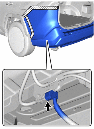
w/ TOYOTA Parking Assist-sensor System, w/ Hands Free Power Back Door:
Disconnect the connector.
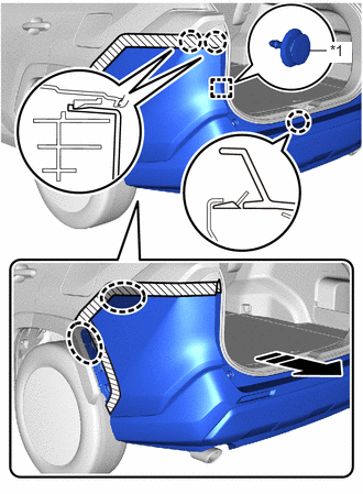
| *1 | Back Door Garnish Retainer |
|
|
Place Hand Here |
|
|
Remove in this Direction |
Detach the claw and back door garnish retainer to remove the rear bumper assembly as shown in the illustration.
- HINT:
-
Use the same procedure for the RH and LH side.
16.REMOVE REAR COMBINATION LIGHT ASSEMBLY LH
- HINT:
-
Perform the following procedure only when replacement of a rear bumper upper retainer LH is necessary.
-
Click hereVehicle Exterior>LIGHTING (EXT)>REAR COMBINATION LIGHT ASSEMBLY>REMOVAL
17.REMOVE REAR COMBINATION LIGHT ASSEMBLY RH
- HINT:
- ·
Perform the following procedure only when replacement of a rear bumper upper retainer RH is necessary.
·Use the same procedure for the RH and LH side.
52563A
18.REMOVE REAR BUMPER UPPER RETAINER LH
- HINT:
-
Perform the following procedure only when replacement of a rear bumper upper retainer LH is necessary.
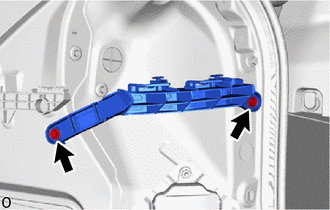
Remove the 2 screws and rear bumper upper retainer LH.
52562B
19.REMOVE REAR BUMPER UPPER RETAINER RH
- HINT:
- ·
Perform the following procedure only when replacement of a rear bumper upper retainer RH is necessary.
·Use the same procedure for the RH and LH side.
52156A
20.REMOVE REAR BUMPER SIDE SUPPORT LH
- HINT:
-
Perform the following procedure only when replacement of a rear bumper side support LH is necessary.
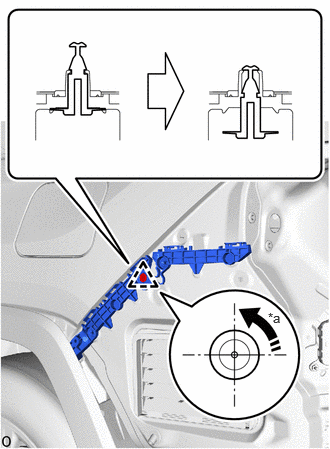
| *a | 90° |
|
|
Remove in this Direction |
Using a screwdriver, turn the clip 90° and detach the clip as shown in the illustration.
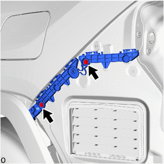
Remove the 2 screws.
|
|
Remove in this Direction |
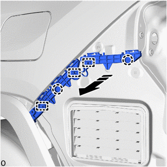
Detach the guide and claw and remove the rear bumper side support LH as shown in the illustration.
52155A
21.REMOVE REAR BUMPER SIDE SUPPORT RH
- HINT:
- ·
Perform the following procedure only when replacement of a rear bumper side support RH is necessary.
·Use the same procedure for the RH and LH side.
52023
22.REMOVE REAR BUMPER REINFORCEMENT SUB-ASSEMBLY
- HINT:
-
Perform the following procedure only when replacement of a rear bumper reinforcement sub-assembly is necessary.
for Type A:
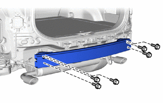
Remove the 6 bolts.
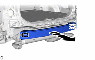
|
|
Remove in this Direction |
Detach the guide and remove the rear bumper reinforcement sub-assembly as shown in the illustration.
for Type B:
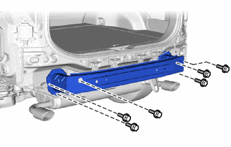
Remove the 6 bolts.
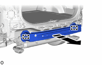
|
|
Remove in this Direction |
Detach the guide and remove the rear bumper reinforcement sub-assembly as shown in the illustration.