AXLE AND DIFFERENTIAL REAR DIFFERENTIAL SIDE GEAR SHAFT OIL SEAL(for Torque Vectoring Differential) REPLACEMENT
CAUTION / NOTICE / HINT
The necessary procedures (adjustment, calibration, initialization, or registration) that must be performed after parts are removed and installed, or replaced during rear differential carrier oil seal and transmission coupling dust seal removal/installation are shown below.
| Replaced Part or Performed Procedure | Necessary Procedure | Effect/Inoperative Function when Necessary Procedure not Performed | Link |
|---|---|---|---|
|
*: When performing learning using the GTS. Click here( |
|||
| Battery terminal is disconnected/reconnected | Drive the vehicle until stop and start control is permitted (approximately 5 to 60 minutes) | Stop and start system | for A25A-FKS:( ) for M20A-FKS:( )
|
| Perform steering sensor zero point calibration | Lane control system | ()
|
|
| Parking support brake system (for Gasoline model)* | |||
| Pre-collision system | |||
| Memorize steering angle neutral point | Parking assist monitor system | ()
|
|
| Panoramic view monitor system (for Gasoline model) | ()
|
||
| Reset back door close position | Power back door system (for Gasoline model) | ()
|
|
| Power back door initialization | Power door lock control system | ()
|
|
| Electro magnetic control coupling sub-assembly | ·
ECU data save ·
ECU data initialization ·
ECU data write |
Dynamic torque vectoring AWD system | ()
|
| Rear electro magnetic control clutch sub-assembly (rear differential carrier assembly) | Disconnect system function check | ||
| Rear wheel alignment adjustment | ·
Perform reset memory ·
Perform acceleration sensor zero point calibration and store system information memorization. |
·
VSC is disabled or malfunctions ·
DTCs are output ·
Slip indicator light illuminates ·
ABS warning light illuminates |
()
|
| Suspension, tires, etc.
(The vehicle height changes because of suspension or tire replacement.) |
·
Ultrasonic sensor detection angle ·
Ultrasonic sensor detection angle registration |
Parking Support Brake System (for Gasoline model) | ()
|
| Television camera assembly optical axis (Back camera position setting) | Parking Assist Monitor System | ()
|
|
·
Parking assist ECU initialization ·
Adjust steering angle |
Panoramic View Monitor System (for Gasoline model) | ()
|
|
| Perform headlight ECU sub-assembly LH initialization | Lighting System (EXT) | ()
|
|
| Gas leak from exhaust system is repaired | Inspection After Repair | ·
Poor idle, etc. ·
Engine start function, etc. |
·
for A25A-FKS w/ Canister Pump Module: ( ·
for A25A-FKS w/o Canister Pump Module: ( ·
for M20A-FKS: ( |
- CAUTION:
-
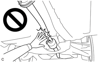
-
To prevent burns, do not touch the engine, exhaust pipe or other high temperature components while the engine is hot.
- NOTICE:
-
After the ignition switch is turned off, the navigation system requires approximately a minute to record various types of memory and settings. As a result, after turning the ignition switch off, wait a minute or more before disconnecting the cable from the negative (-) auxiliary battery terminal.
- HINT:
- ·
Use the same procedure for the RH side and LH side.
·The following procedure is for the LH side.
PROCEDURE

 42340B
1.REMOVE REAR DRIVE SHAFT ASSEMBLY LH
41330M
2.REMOVE TRANSMISSION COUPLING DUST SEAL
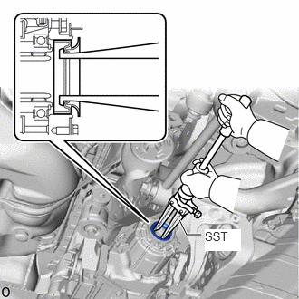
Using SST, tap out the transmission coupling dust seal.
- SST
- 09308-00010
- NOTICE:
-
Be careful not to damage the electro magnetic control coupling sub-assembly.
41110
3.REMOVE TORQUE VECTORING DIFFERENTIAL CARRIER ASSEMBLY
31364D
4.REMOVE CLUTCH CONTROL SOLENOID WIRE
5.REMOVE WIRE HARNESS CLAMP BRACKET
41173
6.REMOVE DIFFERENTIAL DISCONNECT COVER
41173A
7.REMOVE NO. 2 DIFFERENTIAL DISCONNECT COVER
8.REMOVE ELECTRO MAGNETIC CONTROL COUPLING SUB-ASSEMBLY (for LH Side)
9.REMOVE ELECTRO MAGNETIC CONTROL COUPLING SUB-ASSEMBLY (for RH Side)
- HINT:
-
Perform the same procedure as for the LH side.
41110
10.SECURE REAR DIFFERENTIAL CARRIER ASSEMBLY
41201C
11.REMOVE REAR DIFFERENTIAL CARRIER OIL SEAL (for LH Side)
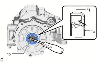
| *1 | Rear Differential Carrier Oil Seal |
| *a | Cut Position |
| *b | Protective Tape |
Using a knife, cut off the lip of the rear differential carrier oil seal.
Using a screwdriver with its tip wrapped with protective tape, pry out the rear differential carrier oil seal.
- NOTICE:
-
Be careful not to damage the rear differential carrier assembly.
41201C
12.REMOVE REAR DIFFERENTIAL CARRIER OIL SEAL (for RH Side)
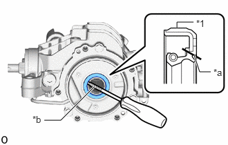
| *1 | Rear Differential Carrier Oil Seal |
| *a | Cut Position |
| *b | Protective Tape |
Using a knife, cut off the lip of the rear differential carrier oil seal.
Using a screwdriver with its tip wrapped with protective tape, pry out the rear differential carrier oil seal.
- NOTICE:
-
Be careful not to damage the rear differential carrier assembly.
41201C
13.INSTALL REAR DIFFERENTIAL CARRIER OIL SEAL (for LH Side)
Coat the lip of a new rear differential carrier oil seal with MP grease.
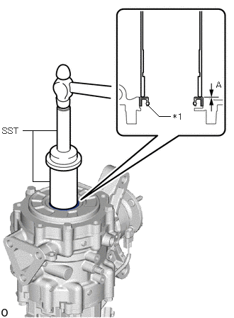
| *1 | Rear Differential Carrier Oil Seal |
Using SST and a hammer, install the rear differential carrier oil seal.
- SST
- 09523-36010
09223-46011
- Standard Distance (A):
-0.5 to 0.5 mm (-0.0197 to 0.0197 in.)
- NOTICE:
- ·
Install the rear differential carrier oil seal uniformly.
·Press fit the rear differential carrier oil seal straight.
·Do not damage the rear differential carrier oil seal.
·Do not excessively press in the rear differential carrier oil seal.
·Make sure to install the rear differential carrier oil seal as specified, otherwise a malfunction such as an oil leak may occur.
41201C
14.INSTALL REAR DIFFERENTIAL CARRIER OIL SEAL (for RH Side)
Coat the lip of a new rear differential carrier oil seal with MP grease.
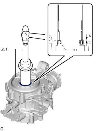
| *1 | Rear Differential Carrier Oil Seal |
Using SST and a hammer, install the rear differential carrier oil seal.
- SST
- 09523-36010
09223-46011
- Standard Distance (A):
-0.5 to 0.5 mm (-0.0197 to 0.0197 in.)
- NOTICE:
- ·
Install the rear differential carrier oil seal uniformly.
·Press fit the rear differential carrier oil seal straight.
·Do not damage the rear differential carrier oil seal.
·Do not excessively press in the rear differential carrier oil seal.
·Make sure to install the rear differential carrier oil seal as specified, otherwise a malfunction such as an oil leak may occur.
15.INSTALL ELECTRO MAGNETIC CONTROL COUPLING SUB-ASSEMBLY (for LH Side)
16.INSTALL ELECTRO MAGNETIC CONTROL COUPLING SUB-ASSEMBLY (for RH Side)
- HINT:
-
Perform the same procedure as for the LH side.
41173A
17.INSTALL NO. 2 DIFFERENTIAL DISCONNECT COVER
41173
18.INSTALL DIFFERENTIAL DISCONNECT COVER
19.INSTALL WIRE HARNESS CLAMP BRACKET
31364D
20.INSTALL CLUTCH CONTROL SOLENOID WIRE
41110
21.INSTALL TORQUE VECTORING DIFFERENTIAL CARRIER ASSEMBLY
41330M
22.INSTALL TRANSMISSION COUPLING DUST SEAL
Coat the lip of a new transmission coupling dust seal with MP grease.
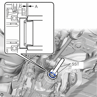
Using SST and a hammer, install the transmission coupling dust seal to the electro magnetic control coupling sub-assembly.
- SST
- 09316-10010
09950-70010 (09951-07150)
- Standard Distance (A):
2.0 to 2.8 mm (0.0788 to 0.1102 in.)
- NOTICE:
- ·
Install the transmission coupling dust seal uniformly.
·Press fit the transmission coupling dust seal straight.
·Do not damage the transmission coupling dust seal.
·Do not excessively press in the transmission coupling dust seal.
·Make sure to install the transmission coupling dust seal as specified, otherwise a malfunction such as an oil leak may occur.
42340B
23.INSTALL REAR DRIVE SHAFT ASSEMBLY LH