CAMSHAFT > INSTALLATION |
| 1. INSTALL CAMSHAFT SETTING OIL SEAL |
|
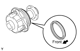
Apply MP grease to the lip of a new oil seal.
Insert 2 new oil seals into the camshaft timing tube until they reach the stopper.
| 2. INSTALL CAMSHAFT TIMING TUBE ASSEMBLY |
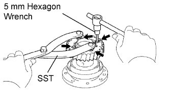 |
Align the timing tube knock pin with the knock pin groove of the drive gear, and temporarily install the drive gear with the 4 bolts.
Using SST and a 5 mm hexagon wrench, uniformly tighten the 4 bolts in several steps.
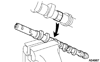 |
Mount the hexagonal portion of the camshaft in a vise.
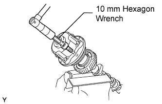 |
Align the camshaft knock pin with the knock pin groove of the timing tube, and push the timing tube by hand until it touches the bottom.
Using a 10 mm hexagon wrench, install the bolt.
Install the seal washer and screw plug.
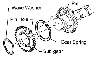
| 3. INSTALL NO. 3 CAMSHAFT SUB GEAR |
 |
 |
Install the gear spring, sub-gear and wave washer.
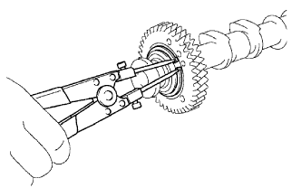
Using snap ring pliers, install the snap ring.
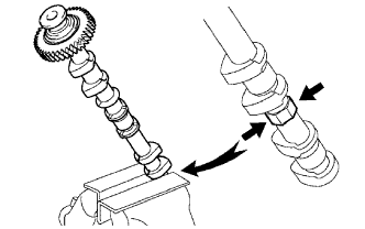 |
Mount the hexagonal portion of the camshaft in a vise.
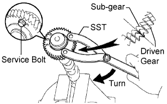 |
Using SST, align the holes of the driven gear and sub-gear by turning the sub-gear clockwise, and temporarily install a service bolt.
| Thread Diameter | Thread Pitch | Bolt Length |
| 6 mm | 1.0 mm | 16 to 20 mm (0.630 to 0.787 in.) |
Align the gear teeth of the driven gear and sub-gear, and tighten the service bolt.
| 4. INSTALL CAMSHAFT SUB-ASSEMBLY (for Bank 1) |
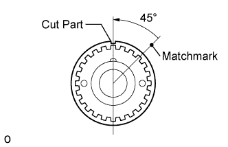 |
Check that the timing mark of the crankshaft timing pulley is in the position shown in the illustration, and that the piston is below the TDC of compression.
Apply a light coat of engine oil to the cam lobe and gear of the camshaft and also the journal of the cylinder head.
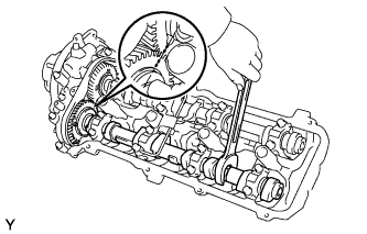 |
Using a wrench, align the timing marks (2 dot marks each) of the camshaft drive and driven main gears, and set the No. 3 and No. 4 camshafts in place.
Install the bearing cap.
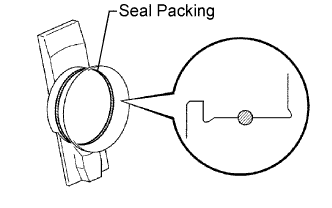 |
Apply seal packing to the camshaft housing plug groove.
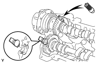 |
Install the camshaft housing plug and oil control valve filter to the cylinder head as shown in the illustration.
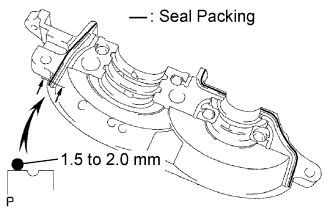 |
Apply seal packing to the No. 1 bearing cap as shown in the illustration.
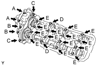 |
Install 4 new seal washers to the bearing cap bolts (A and B).
Apply a light coat of engine oil to the threads and under the heads of the bearing cap bolts (C to E).
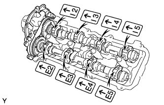 |
Temporarily install the oil feed pipe and bearing caps with the 22 bolts, as shown in the illustration.
| Item | Length |
| Bolt A with seal washer | 94 mm (3.70 in.) |
| Bolt B with seal washer | 72 mm (2.84 in.) |
| Bolt C | 25 mm (0.984 in.) |
| Bolt D | 55 mm (2.17 in.) |
| Bolt E | 40 mm (1.58 in.) |
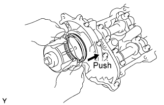 |
Push in the camshaft setting oil seal.
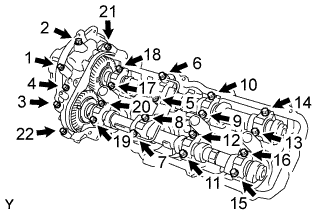 |
Uniformly tighten the 22 bearing cap bolts in several steps, in the sequence shown in the illustration.
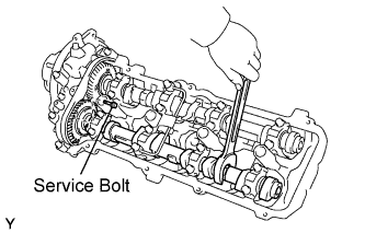 |
Bring the service bolt installed in the driven sub-gear upward by turning the hexagonal portion of the camshaft with a wrench.
Remove the service bolt.
| 5. INSTALL REAR TIMING BELT PLATE LH |
Install the No. 1 timing belt plate and No. 2 timing plate with the 3 bolts.
| 6. INSTALL CAMSHAFT TIMING PULLEY SUB-ASSEMBLY LH |
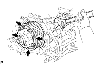 |
Align the camshaft timing tube knock pin with the knock pin groove of the timing pulley.
Temporarily install the 4 bolts of the camshaft timing pulley.
Hold the hexagonal portion of the camshaft with a wrench.
Using a 5 mm hexagon wrench, tighten the 4 bolts.
| 7. INSTALL CAMSHAFT POSITION SENSOR ASSEMBLY |
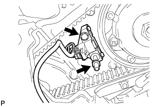 |
Install the camshaft position sensor with the bolt and stud bolt.
| 8. INSTALL CAMSHAFT (for Bank 2) |
|
Check that the timing mark of the crankshaft timing pulley is in the position shown in the illustration, and that the piston is below the TDC of compression.
Apply a light coat of engine oil to the cam lobe and gear of the camshaft and also the journal of the cylinder head.
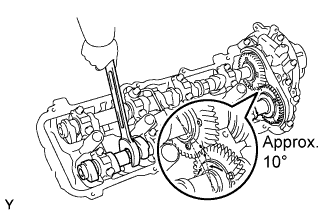 |
Using a wrench, align the timing marks (1 dot marks each) of the camshaft drive and driven main gears, and set the No. 1 and No. 2 camshafts in place.
Install the bearing cap.
|
Apply seal packing to the camshaft housing plug groove.
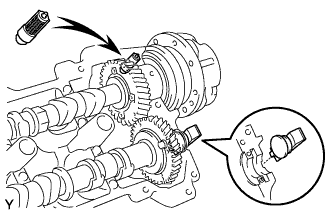 |
Install the camshaft housing plug and oil control valve filter to the cylinder head as shown in the illustration.
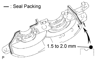 |
Apply seal packing to the No. 1 bearing cap as shown in the illustration.
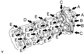 |
Install 4 new seal washers to the bearing cap bolts (A and B).
Apply a light coat of engine oil to the threads and under the heads of the bearing cap bolts (C to E).
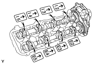 |
Temporarily install the oil feed pipe and bearing caps with the 22 bolts, as shown in the illustration.
| Item | Length |
| Bolt A with seal washer | 94 mm (3.70 in.) |
| Bolt B with seal washer | 72 mm (2.84 in.) |
| Bolt C | 25 mm (0.984 in.) |
| Bolt D | 55 mm (2.17 in.) |
| Bolt E | 40 mm (1.58 in.) |
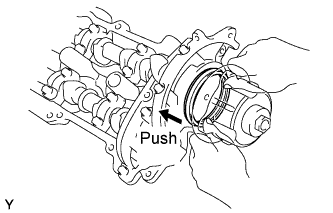 |
Push in the camshaft setting oil seal.
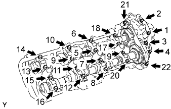 |
Uniformly tighten the 22 bearing cap bolts in several steps, in the sequence shown in the illustration.
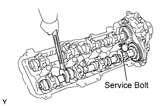 |
Bring the service bolt installed in the driven sub-gear upward by turning the hexagonal portion of the camshaft with a wrench.
Remove the service bolt.
| 9. INSTALL REAR TIMING BELT PLATE RH |
Install the No. 1 timing belt plate and No. 2 timing belt plate with the 4 bolts.
| 10. INSTALL CAMSHAFT TIMING PULLEY |
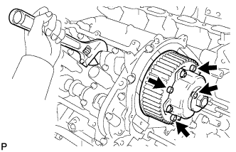 |
Align the camshaft timing tube knock pin with the knock pin groove of the timing pulley.
Temporarily install the 4 bolts of the camshaft timing pulley.
Hold the hexagonal portion of the camshaft with a wrench.
Using a 5 mm hexagon wrench, tighten the 4 bolts.
| 11. INSTALL TIMING BELT |
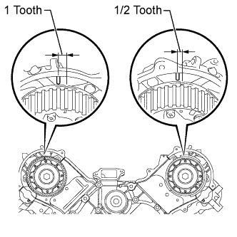 |
Set the No. 1 cylinder to TDC/compression.
Turn the hexagonal portion of the camshaft to align the timing marks of the camshaft timing pulleys and timing belt plates.
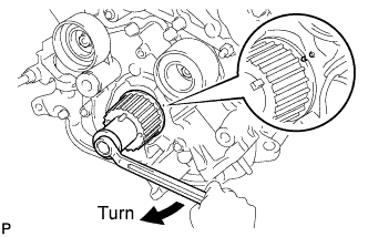 |
Using the pulley set bolt, turn the crankshaft to align the timing marks of the crankshaft timing pulley and oil pump body.
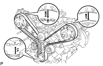 |
Install the timing belt.
Remove any oil or water from each pulley, and keep them clean.
Face the front mark (arrow) on the timing belt forward.
Align the timing marks on the timing belt and crankshaft timing pulley, and the timing belt and camshaft timing pulleys, and install the timing belt.
 |
Install the belt tensioner.
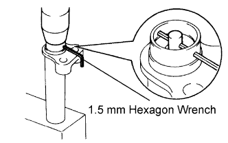
Using a press, slowly press in the push rod using 981 to 9807 N (100 to 1000 kgf, 220.5 to 2204.7 lbf) of force.
Align the holes of the push rod and housing, and pass a 1.5 mm hexagon wrench through the holes to keep the setting position of the push rod.
Release the press.
Install the dust boot to the belt tensioner.
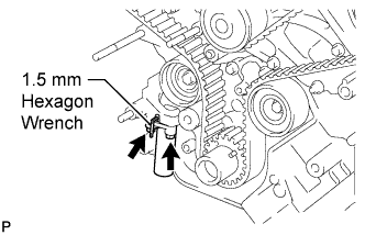 |
Temporarily install the belt tensioner with the 2 bolts.
Tighten the 2 bolts.
Using pliers, remove the 1.5 mm hexagon wrench from the timing belt tensioner.
| 12. CHECK NO. 1 CYLINDER TO TDC/COMPRESSION |
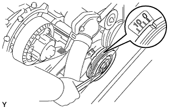 |
Turn the crankshaft pulley to align its notch with timing mark "0" of the No. 1 timing belt cover.
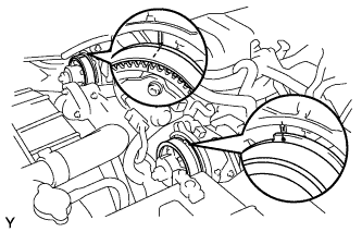 |
Check that the timing marks of the camshaft timing pulleys and timing belt rear plates are aligned.
If not, turn the crankshaft 1 complete revolution (360°) and align the marks as above.
| 13. INSPECT VALVE CLEARANCE |
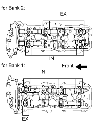 |
Check only the valves indicated.
Using a feeler gauge, measure the clearance between the valve lifter and camshaft.
| Item | Specified Condition |
| Intake | 0.15 to 0.25 mm (0.00591 to 0.00984 in.) |
| Exhaust | 0.25 to 0.35 mm (0.00984 to 0.0138 in.) |
Record the out-of-specification valve clearance measurements. They will be used later to determine the required replacement adjusting shim.
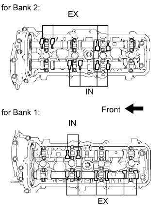 |
Turn the crankshaft 1 complete revolution (360°) and align the camshaft timing marks.
Check only the valves indicated in the illustration.
Using a feeler gauge, measure the clearance between the valve lifter and camshaft.
| Item | Specified Condition |
| Intake | 0.15 to 0.25 mm (0.00591 to 0.00984 in) |
| Exhaust | 0.25 to 0.35 mm (0.00984 to 0.0138 in.) |
Record the out-of-specification valve clearance measurements. They will be used later to determine the required replacement adjusting shim.
| 14. ADJUST VALVE CLEARANCE |
Remove the timing belt (Click here).
Remove the camshaft (Click here).
Remove the valve lifter and adjusting shim.
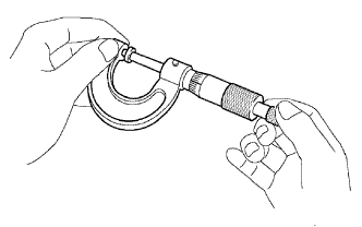 |
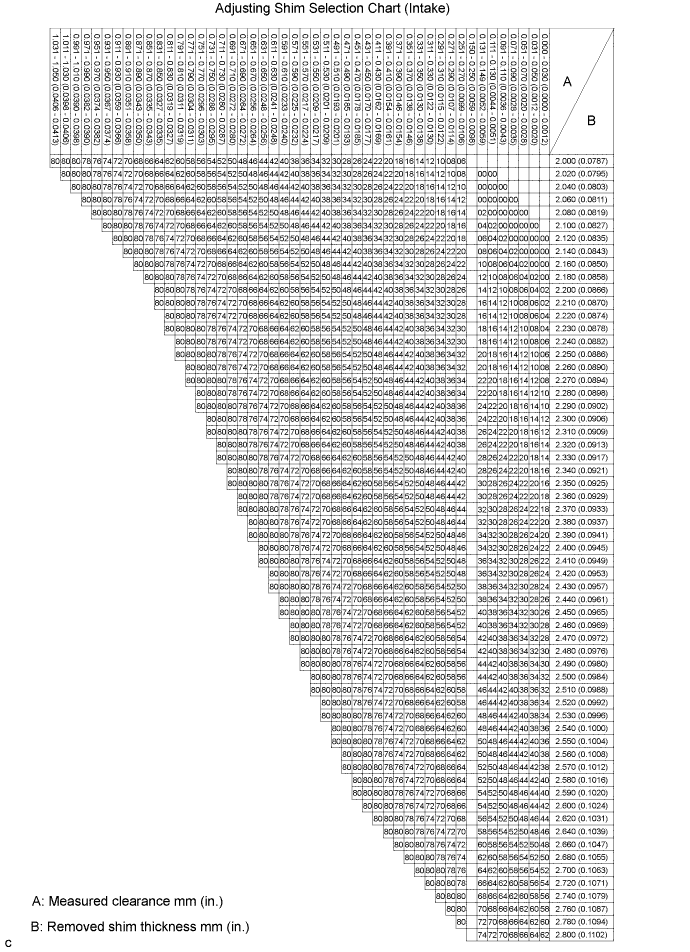
Determine the replacement adjusting shim size according to the formula or charts below.
Using a micrometer, measure the thickness of the removed shim.
Calculate the thickness of a new shim so that the valve clearance comes within the specified value.
Select a new shim with a thickness as close as possible to the calculated value.
| Shim No. | Thickness | Shim No. | Thickness | Shim No. | Thickness |
| 00 | 2.000 mm (0.0787 in.) | 28 | 2.280 mm (0.0898 in.) | 56 | 2.560 mm (0.1008 in.) |
| 02 | 2.020 mm (0.0795 in.) | 30 | 2.300 mm (0.0906 in.) | 58 | 2.580 mm (0.1016 in.) |
| 04 | 2.040 mm (0.0803 in.) | 32 | 2.320 mm (0.0913 in.) | 60 | 2.600 mm (0.1024 in.) |
| 06 | 2.060 mm (0.0811 in.) | 34 | 2.340 mm (0.0921 in.) | 62 | 2.620 mm (0.1031 in.) |
| 08 | 2.080 mm (0.0819 in.) | 36 | 2.360 mm (0.0929 in.) | 64 | 2.640 mm (0.1039 in.) |
| 10 | 2.100 mm (0.0827 in.) | 38 | 2.380 mm (0.0937 in.) | 66 | 2.660 mm (0.1047 in.) |
| 12 | 2.120 mm (0.0835 in.) | 40 | 2.400 mm (0.0945 in.) | 68 | 2.680 mm (0.1055 in.) |
| 14 | 2.140 mm (0.0843 in.) | 42 | 2.420 mm (0.0953 in.) | 70 | 2.700 mm (0.1063 in.) |
| 16 | 2.160 mm (0.0850 in.) | 44 | 2.440 mm (0.0961 in.) | 72 | 2.720 mm (0.1071 in.) |
| 18 | 2.180 mm (0.0858 in.) | 46 | 2.460 mm (0.0969 in.) | 74 | 2.740 mm (0.1079 in.) |
| 20 | 2.200 mm (0.0866 in.) | 48 | 2.480 mm (0.0976 in.) | 76 | 2.760 mm (0.1087 in.) |
| 22 | 2.220 mm (0.0874 in.) | 50 | 2.500 mm (0.0984 in.) | 78 | 2.780 mm (0.1094 in.) |
| 24 | 2.240 mm (0.0882 in.) | 52 | 2.520 mm (0.0992 in.) | 80 | 2.800 mm (0.1102 in.) |
| 26 | 2.260 mm (0.0890 in.) | 54 | 2.540 mm (0.1000 in.) | - | - |
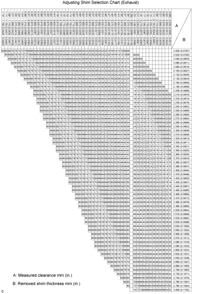
| Shim No. | Thickness | Shim No. | Thickness | Shim No. | Thickness |
| 00 | 2.000 mm (0.0787 in.) | 28 | 2.280 mm (0.0898 in.) | 56 | 2.560 mm (0.1008 in.) |
| 02 | 2.020 mm (0.0795 in.) | 30 | 2.300 mm (0.0906 in.) | 58 | 2.580 mm (0.1016 in.) |
| 04 | 2.040 mm (0.0803 in.) | 32 | 2.320 mm (0.0913 in.) | 60 | 2.600 mm (0.1024 in.) |
| 06 | 2.060 mm (0.0811 in.) | 34 | 2.340 mm (0.0921 in.) | 62 | 2.620 mm (0.1031 in.) |
| 08 | 2.080 mm (0.0819 in.) | 36 | 2.360 mm (0.0929 in.) | 64 | 2.640 mm (0.1039 in.) |
| 10 | 2.100 mm (0.0827 in.) | 38 | 2.380 mm (0.0937 in.) | 66 | 2.660 mm (0.1047 in.) |
| 12 | 2.120 mm (0.0835 in.) | 40 | 2.400 mm (0.0945 in.) | 68 | 2.680 mm (0.1055 in.) |
| 14 | 2.140 mm (0.0843 in.) | 42 | 2.420 mm (0.0953 in.) | 70 | 2.700 mm (0.1063 in.) |
| 16 | 2.160 mm (0.0850 in.) | 44 | 2.440 mm (0.0961 in.) | 72 | 2.720 mm (0.1071 in.) |
| 18 | 2.180 mm (0.0858 in.) | 46 | 2.460 mm (0.0969 in.) | 74 | 2.740 mm (0.1079 in.) |
| 20 | 2.200 mm (0.0866 in.) | 48 | 2.480 mm (0.0976 in.) | 76 | 2.760 mm (0.1087 in.) |
| 22 | 2.220 mm (0.0874 in.) | 50 | 2.500 mm (0.0984 in.) | 78 | 2.780 mm (0.1094 in.) |
| 24 | 2.240 mm (0.0882 in.) | 52 | 2.520 mm (0.0992 in.) | 80 | 2.800 mm (0.1102 in.) |
| 26 | 2.260 mm (0.0890 in.) | 54 | 2.540 mm (0.1000 in.) | - | - |
Place a new adjusting shim on the valve.
Place the valve lifter.
Install the camshaft (Click here ).
Install the timing belt (Click here).
Check the valve clearance.
If the result is not as specified, adjust the valve clearance.
| 15. INSTALL CYLINDER HEAD COVER SUB-ASSEMBLY LH |
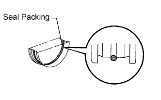 |
Apply seal packing to the semicircular plug grooves.
Install the 2 semicircular plugs to the cylinder heads.
Install the gasket to the cylinder head cover.
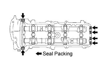 |
Apply seal packing to the cylinder head as shown in the illustration.
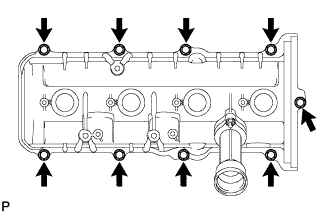 |
Install the cylinder head cover with the 9 bolts. Uniformly tighten the bolts in several steps.
| 16. INSTALL VENTILATION HOSE |
Install the ventilation hose.
| 17. INSTALL CYLINDER HEAD COVER SUB-ASSEMBLY |
|
Apply seal packing to the semicircular plug grooves.
Install the 2 semicircular plugs to the cylinder heads.
Install the gasket to the cylinder head cover.
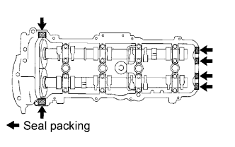 |
Apply seal packing to the cylinder head as shown in the illustration.
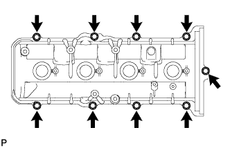 |
Install the cylinder head cover with the 9 bolts. Uniformly tighten the bolts in several steps.
| 18. INSTALL SPARK PLUG |
Using a 16 mm plug wrench, install the 8 spark plugs.
| 19. INSTALL IGNITION COIL ASSEMBLY |
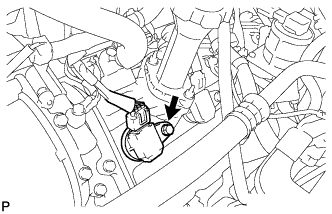 |
Install the 8 ignition coil assemblies with the 8 bolts.
Connect the 8 ignition coil assembly connectors.
| 20. INSTALL NO. 1 WATER PIPE SUB-ASSEMBLY |
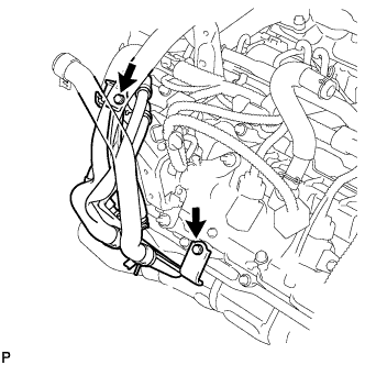 |
Install the water by-pass pipe with the 2 bolts.
| 21. CONNECT INLET HEATER WATER HOSE D |
Connect the inlet heater water hose D to the No. 3 water by-pass pipe.
| 22. CONNECT NO. 5 WATER BY-PASS HOSE |
Connect the No. 5 water by-pass hose to the No. 3 water by-pass pipe.
| 23. INSTALL ENGINE WIRE |
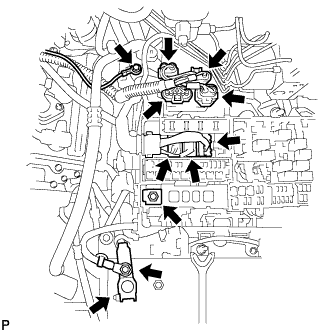 |
Connect the 3 connectors to the engine room junction block.
Install the engine wire with the nut.
Connect the 4 air injection control driver connectors.
Install the ground wire with the bolt.
Connect the positive (+) battery terminal and install the engine wire with the nut.
| 24. INSTALL AIR SWITCHING VALVE ASSEMBLY (for Bank 1) |
Install the air switching valve assembly (Click here).
| 25. INSTALL FUEL PRESSURE PULSATION DAMPER ASSEMBLY |
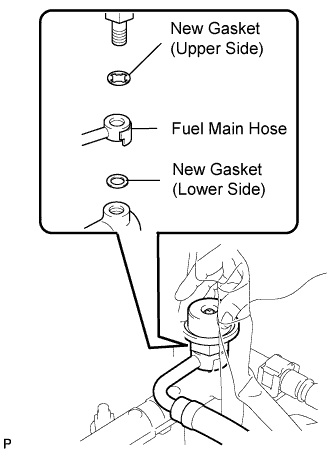 |
Install 2 new gaskets and the fuel main hose with the fuel pressure pulsation damper.
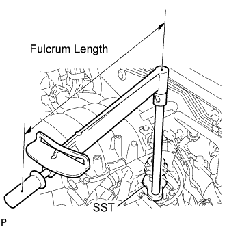 |
Using SST, tighten the union bolt.
| 26. CONNECT NO. 1 FUEL PIPE SUB-ASSEMBLY |
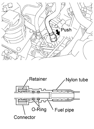 |
Connect the No. 1 fuel pipe sub-assembly.
| 27. CONNECT NO. 2 FUEL PIPE SUB-ASSEMBLY |
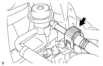 |
Connect the No. 2 fuel pipe sub-assembly (Click here).
| 28. INSTALL FUEL PIPE CLAMP |
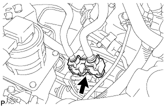 |
Install the fuel pipe clamp.
| 29. INSTALL VACUUM HOSE ASSEMBLY |
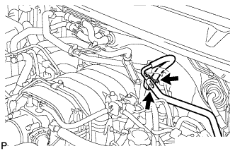 |
Connect the vacuum hose assembly to the intake manifold assembly.
Install the vacuum hose assembly with the bolt.
| 30. INSTALL NO. 1 CRANKSHAFT POSITION SENSOR PLATE |
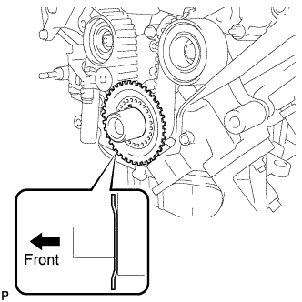 |
Install the sensor plate as shown in the illustration.
| 31. INSTALL NO. 1 TIMING BELT COVER |
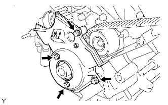 |
Install the cover spacer and gasket.
Install the timing belt cover with the 4 bolts.
| 32. INSTALL CRANKSHAFT DAMPER SUB-ASSEMBLY |
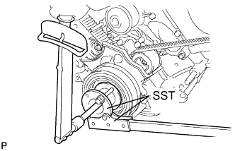 |
Align the pulley set key with the key groove of the crankshaft damper.
Using SST, hold the crankshaft pulley and install the pulley bolt.
| 33. INSTALL FAN BRACKET SUB-ASSEMBLY |
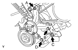 |
Install the fan bracket with the 2 bolts and 2 nuts.
| 34. INSTALL V-RIBBED BELT TENSIONER ASSEMBLY |
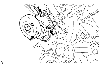 |
Install the belt tensioner with the bolt and 2 nuts.
| 35. INSTALL NO. 2 TIMING BELT COVER SUB-ASSEMBLY |
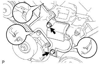 |
Install the timing belt cover and fit the claws and pins into each part.
Install the 2 bolts.
| 36. INSTALL NO. 3 TIMING BELT COVER SUB-ASSEMBLY LH |
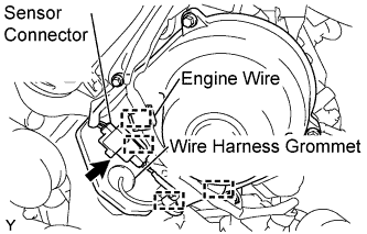 |
Pass the camshaft position sensor wire through the cover hole.
Install the cover with the 4 bolts.
Install the wire harness grommet to the belt cover.
Connect the sensor connector.
Install the sensor wire to the wire clamps on the cover.
Connect the engine wire to the 4 wire clamps on the cover.
| 37. INSTALL NO. 2 TIMING CHAIN OR BELT COVER |
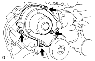 |
Install the cover with the 3 bolts and nut.
| 38. INSTALL NO. 2 IDLER PULLEY SUB-ASSEMBLY |
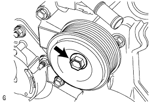 |
Install the idler pulley and cover plate with the bolt.
| 39. INSTALL OIL COOLER PIPE |
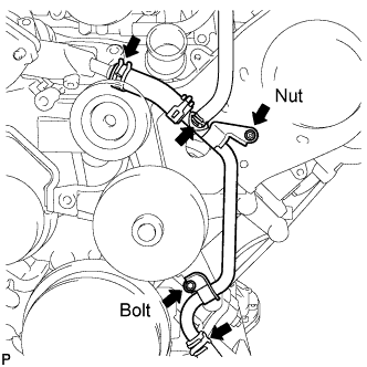 |
Connect the 3 water by-pass hoses.
Install the oil cooler pipe with the cap nut and bolt.
| 40. INSTALL COOLER COMPRESSOR ASSEMBLY |
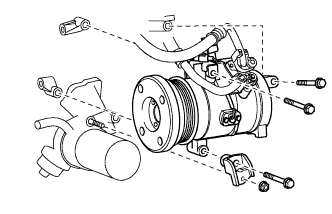 |
Connect the compressor. Then install it and the No. 1 compressor stay with the nut and 3 bolts.
Connect the connector.
| 41. INSTALL GENERATOR ASSEMBLY |
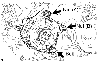 |
Install the generator assembly with the bolt and 2 nuts.
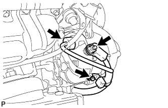 |
Connect the generator connector.
Connect the generator wire with the nut.
Install the terminal cap.
Install the harness bracket to the generator assembly with the bolt.
| 42. INSTALL VANE PUMP ASSEMBLY |
Install the vane pump assembly with 2 bolts.
Connect the connector.
| 43. INSTALL FAN SHROUD (w/ Trailer Towing System) |
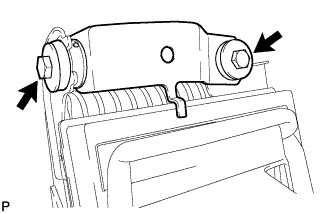 |
Install the oil cooler support bracket with the 2 bolts.
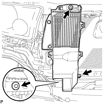 |
Temporarily place the air cooled oil cooler assembly on the radiator support.
Install the air cooled oil cooler assembly with the 3 bolts.
| 44. INSTALL FAN SHROUD (w/o Trailer Towing System) |
Install the fan pulley to the water pump.
Place the fan shroud together with the fluid coupling fan between the radiator and engine.
Install the fluid coupling fan to the water pump with the 4 nuts. Tighten the nuts as much as possible by hand.
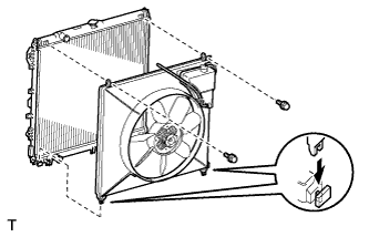 |
Attach the shroud claws to the radiator as shown in the illustration.
Install the shroud with the 2 bolts.
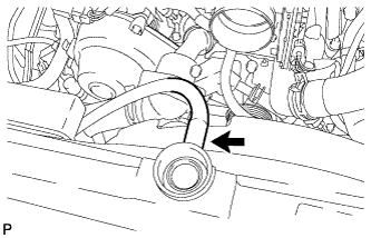 |
Connect the reservoir hose.
Install the fan and generator V-belt .
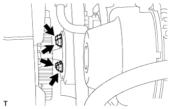 |
Tighten the 4 nuts of the fluid coupling fan.
| 45. CONNECT OUTLET RADIATOR HOSE |
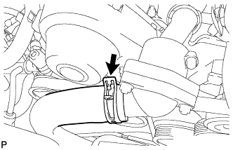 |
Connect the outlet radiator hose.
| 46. CONNECT INLET RADIATOR HOSE |
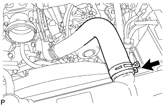 |
Connect the inlet radiator hose.
| 47. INSTALL AIR CLEANER ASSEMBLY WITH AIR CLEANER HOSE |
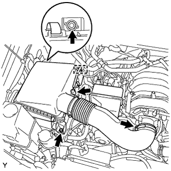 |
Install the air cleaner assembly with air cleaner hose with the 2 bolts.
Tighten the air cleaner hose clamp.
Connect the vacuum hose and No. 2 ventilation hose.
Connect the air flow meter connector.
Install the wire harness to the air cleaner cap.
| 48. INSTALL THROTTLE BODY COVER SUB-ASSEMBLY |
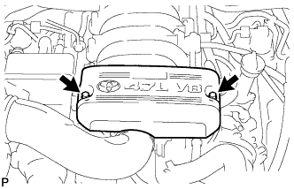 |
Install the throttle body cover sub-assembly with the 2 nuts.
| 49. ADD ENGINE OIL |
Install a new gasket and the drain plug.
Add new oil.
| Oil Grade | Oil Viscosity (SAE) |
| ILSAC multigrade engine oil | 5W-30 (5W-30 is the best choice for this vehicle for good fuel economy and good starting in cold weather.) |
| Item | Specified Condition |
| Drain and refill with oil filter change | 6.2 liters (6.6 US qts, 5.5 Imp. qts) |
| Drain and refill without oil filter change | 5.7 liters (6.0 US qts, 5.0 Imp. qts) |
| Dry fill | 7.1 liters (7.5 US qts, 6.2 Imp. qts) |
Install the oil filler cap.
| 50. ADD ENGINE COOLANT |
Add engine coolant.
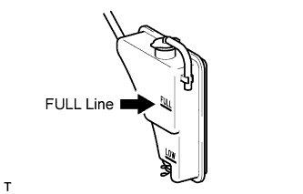 |
Slowly pour coolant into the radiator reservoir until it reaches the FULL line.
Install the reservoir cap.
Press the inlet and outlet radiator hoses several times by hand, and then check the coolant level. If the coolant level is low, add coolant.
Install the radiator cap.
Start the engine and warm it up until the thermostat opens.
Maintain the engine speed at 2000 to 2500 rpm and warm up the engine until the cooling fan operates.
Press the inlet and outlet radiator hoses several times by hand to bleed air.
Stop the engine, and wait until the engine coolant cools down.
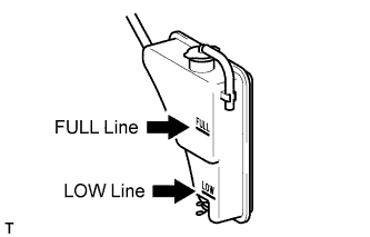 |
If the coolant level is below the LOW line, repeat all of the procedures above.
| 51. CONNECT CABLE TO NEGATIVE BATTERY TERMINAL |
| 52. INSPECT FOR OIL LEAK |
| 53. INSPECT FOR COOLANT LEAK |
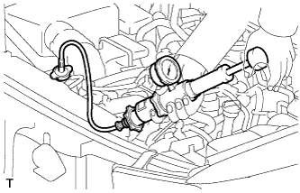 |
Fill the radiator with coolant and attach a radiator cap tester.
Warm up the engine.
Using the radiator cap tester, increase the pressure inside the radiator to 118 kPa (1.2 kgf/cm2, 17 psi), and check that the pressure does not drop. If the pressure drops, check the hoses, radiator and water pump for leaks. If no external leaks are found, check the heater core, cylinder block and head.
| 54. INSPECT FOR FUEL LEAK |
Connect the Techstream to the DLC3.
Turn the ignition switch to ON and turn the Techstream ON.
Techstream:
Enter the following menus: Powertrain / Engine and ECT / Active Test / Control the Fuel Pump / Speed.
Check that there are no fuel leaks after doing maintenance anywhere on the fuel system.
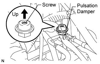 |
Check that the pulsation damper screw rises up when the fuel pump operates.
If the operation is not as specified, check the following parts:
Turn the ignition switch off.
Disconnect the Techstream from the DLC3.
| 55. CHECK ENGINE OIL LEVEL |
Warm up the engine, and then stop the engine and wait for 5 minutes.
Check that the engine oil level is between the low level and full level marks on the dipstick.
If low, check for leakage and add oil up to the full level mark.
| 56. INSPECT IGNITION TIMING |
Warm up and stop the engine.
Allow the engine to warm up to a normal operating temperature.
When using the Techstream:
Connect the Techstream to the DLC3.
Start the engine and idle it.
Push the Techstream main switch ON.
Enter the following menus: Powertrain / Engine / Data List / IGN Advance.
Disconnect the Techstream from the DLC3.
 |
When not using the Techstream:
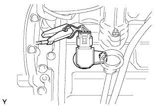
Connect the tester probe of a timing light to the wire of the ignition coil connector for the No. 1 cylinder.
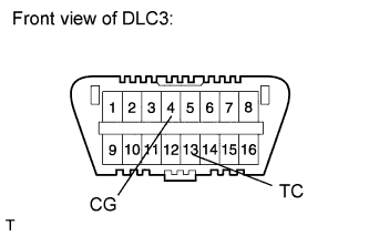 |
Using SST, connect terminals 13 (TC) and 4 (CG) of the DLC3.
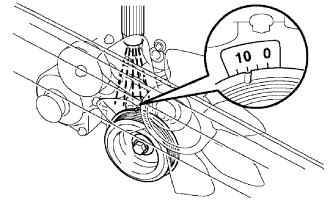 |
Using the timing light, check the ignition timing.
Remove SST from the DLC3.
Disconnect the timing light from the engine.
| 57. INSPECT ENGINE IDLE SPEED |
Warm up and stop the engine.
Allow the engine to warm up to a normal operating temperature.
When using the Techstream:
Connect the Techstream to the DLC3.
Race the engine at 2500 rpm for approximately 90 seconds.
Push the Techstream main switch ON.
Enter the following menus: / Engine / Data List / Engine Speed.
Disconnect the Techstream from the DLC3.
 |
When not using the Techstream:
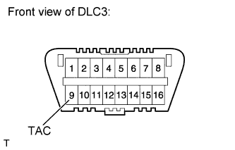
Using SST, connect the tachometer probe to terminal 9 (TAC) of the DLC3.
Race the engine at 2500 rpm for approximately 90 seconds.
Check the idle speed.
Disconnect the tachometer from the DLC3.
| 58. INSTALL NO. 1 ENGINE UNDER COVER |
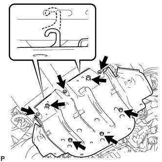 |
Hook the engine under cover onto the vehicle body as shown in the illustration.
Install the 3 screws and 5 bolts.