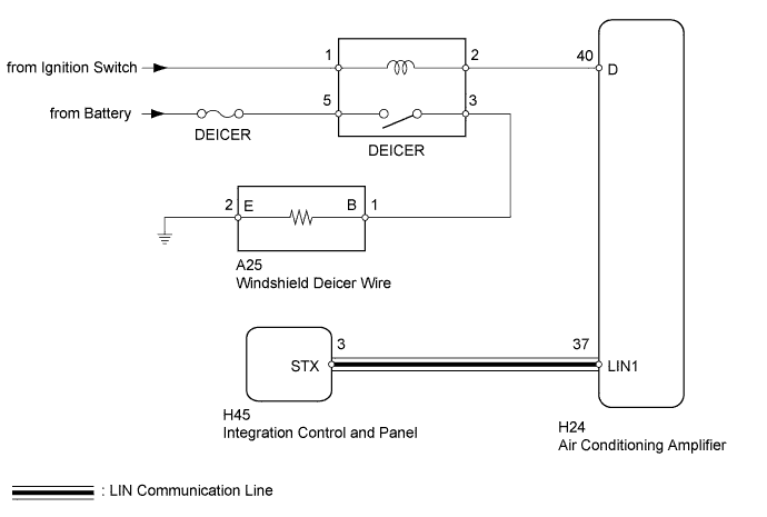
WINDSHIELD DEICER SYSTEM > Windshield Deicer does not Operate |
| 1.PERFORM ACTIVE TEST USING TECHSTREAM (DEICER RELAY) |
Connect the Techstream to the DLC3.
Turn the ignition switch to ON.
Turn the Techstream on.
Enter the following menus: Body Electrical / Air Conditioner / Active Test / Deicer Relay (Front)
Check that the deicer operation.
| Tester Display | Test Part | Control Range | Diagnostic Note |
| Deicer Relay (Front) | Deicer relay operation | OFF or ON | - |
|
| ||||
| OK | |
 |
| 2.CHECK AIR CONDITIONING SYSTEM (LIN COMMUNICATION) |
Operate the integration control and panel to change the set temperature and check that the temperature at the outlets changes.
|
| ||||
| OK | |
|
| 3.REPLACE INTEGRATION CONTROL AND PANEL |
Temporarily replace the integration control and panel with a new or normally functioning one (Click here).
| NEXT | |
|
| 4.CHECK INTEGRATION CONTROL AND PANEL (OPERATION) |
Check that the malfunction disappears.
|
| ||||
| OK | ||
 | ||
| ||
| 5.INSPECT FUSE (DEICER) |
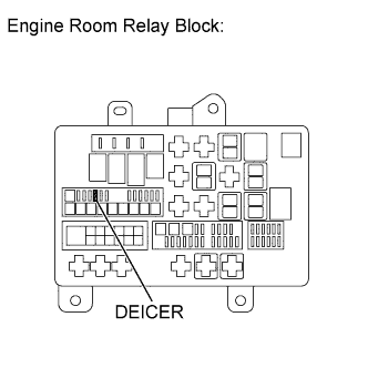 |
Remove the DEICER fuse from the engine room relay block.
Measure the resistance according to the value(s) in the table below.
| Tester Connection | Condition | Specified Condition |
| DEICER fuse | Always | Below 1 Ω |
Reinstall the DEICER fuse.
|
| ||||
| OK | |
|
| 6.INSPECT DEICER RELAY |
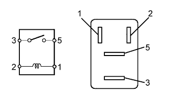 |
Remove the DEICER relay from the engine room relay block.
Measure the resistance according to the value(s) in the table below.
| Tester Connection | Condition | Specified Condition |
| 3 - 5 | When battery voltage is not applied between terminals 1 and 2 | 10 kΩ or higher |
| When battery voltage is applied to terminals 1 and 2 | Below 1 Ω |
Reinstall the DEICER relay.
|
| ||||
| OK | |
|
| 7.CHECK HARNESS AND CONNECTOR (DEICER RELAY - AIR CONDITIONING AMPLIFIER AND BATTERY) |
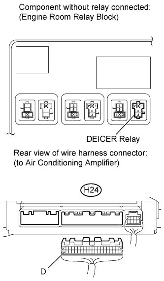 |
Remove the deicer relay from the engine room relay block.
Disconnect the H24 air conditioning amplifier connector.
Measure the voltage according to the value(s) in the table below.
| Tester Connection | Switch Condition | Specified Condition |
| Deicer relay terminal 1 - Body ground | Ignition switch ON | 11 to 14 V |
| Deicer relay terminal 5 - Body ground | Always | 11 to 14 V |
Measure the resistance according to the value(s) in the table below.
| Tester Connection | Condition | Specified Condition |
| Deicer relay terminal 2 - H24-40 (D) | Always | Below 1 Ω |
| Deicer relay terminal 2 - Body ground | Always | 10 kΩ or higher |
Reconnect the air conditioning amplifier connector.
Reinstall the deicer relay.
|
| ||||
| OK | |
|
| 8.CHECK HARNESS AND CONNECTOR (DEICER RELAY - WINDSHIELD DEICER WIRE) |
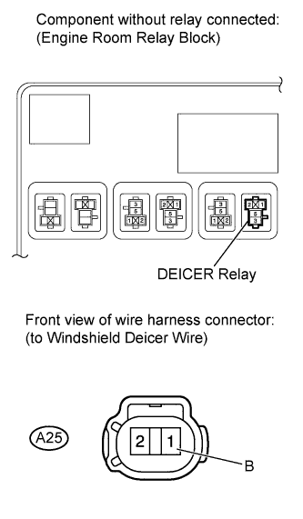 |
Remove the deicer relay from the engine room relay block.
Disconnect the A25 windshield deicer wire connector.
Measure the resistance according to the value(s) in the table below.
| Tester Connection | Condition | Specified Condition |
| A25-1 (B) - Deicer relay terminal 3 | Always | Below 1 Ω |
| Deicer relay terminal 3 - Body ground | Always | 10 kΩ or higher |
Reconnect the A25 windshield deicer wire connector.
Reinstall the deicer relay.
|
| ||||
| OK | |
|
| 9.CHECK HARNESS AND CONNECTOR (WINDSHIELD DEICER WIRE - BODY GROUND) |
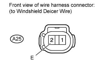 |
Disconnect the A25 windshield deicer wire connector.
Measure the resistance according to the value(s) in the table below.
| Tester Connection | Condition | Specified Condition |
| A25-2 (E) - Body ground | Always | Below 1 Ω |
Reconnect the windshield deicer wire connector.
|
| ||||
| OK | |
|
| 10.CHECK WINDSHIELD DEICER WIRE (SYSTEM VOLTAGE) |
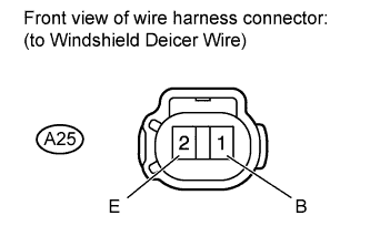 |
Disconnect the A25 windshield deicer wire connector.
Measure the voltage according to the value(s) in the table below.
| Tester Connection | Switch Condition | Specified Condition |
| A25-1 (B) - A25-2 (E) | Ignition switch ON Windshield deicer switch ON | 11 to 14 V |
Reconnect the windshield deicer wire connector.
|
| ||||
| OK | ||
| ||
| ||

