3UR-FBE ENGINE CONTROL SFI SYSTEM Fuel Pressure Switching System
DESCRIPTION
A Flexible Fuel Vehicle (FFV) is a vehicle with an engine that can be used with a high concentration of ethyl alcohol fuel.
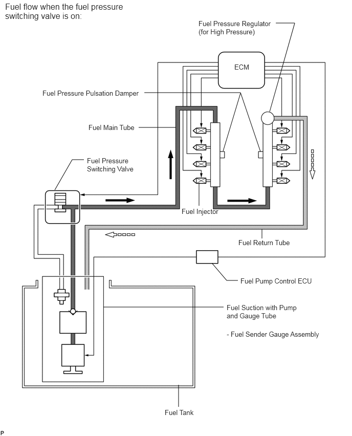
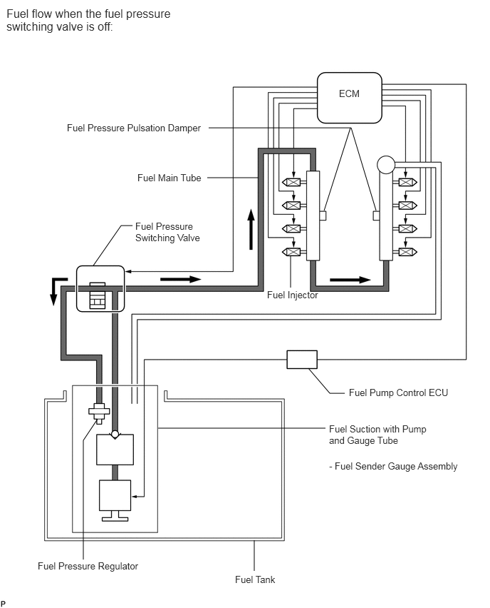
An FFV changes the fuel pressure to a low pressure of 270 to 330 kPa or a high pressure of 370 to 430 kPa using the fuel pressure switching valve.
For example, when starting the engine and during heavy loads while using E85 fuel, the fuel pressure switching valve switches to the high pressure side.
It is necessary to inject more ethanol fuel than gasoline to obtain the same amount of power. Therefore, when a large amount of fuel is required, a high fuel pressure is used.
WIRING DIAGRAM
CAUTION / NOTICE / HINT
- NOTICE:
- ·
Make sure that "Alcohol Density Learning" in the Data List has been completed before performing the following troubleshooting procedures.
When "Alcohol Density Learning" has not been completed, start the engine and drive the vehicle at 32 km/h (20 mph) or more and maintain a constant speed for 2 minutes or more.
·Inspect the fuses for circuits related to this system before performing the following procedure.
- HINT:
-
The engine is difficult to start if the alcohol concentration of the fuel in the fuel tank is high. Therefore, it may be necessary to crank the engine a few times before it starts.
PROCEDURE
Visually check for fuel leaks.
- OK:
No fuel leaks.
- HINT:
- ·
The fuel pressure is normally 270 to 330 kPa when the fuel pressure switching valve is off, and 370 to 430 kPa when the valve is on.
·If there is a fuel leak, the fuel pressure is below 270 kPa when the fuel pressure switching valve is off, and below 370 kPa when the valve is on.
OK
NG
Install the pressure gauge (See page Engine / Hybrid System>3UR-FBE FUEL>FUEL SYSTEM>ON-VEHICLE INSPECTION).
Start the engine.
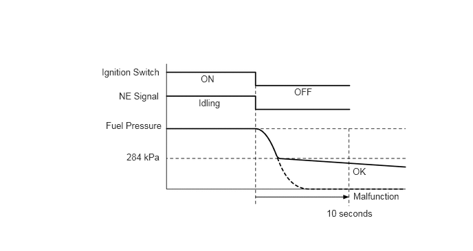
Check that the fuel pressure discharge when the ignition switch is turned off.
- HINT:
-
If the fuel pressure in the high pressure side pressure regulator cannot remain stable, the fuel pressure changes to below 270 kPa when the fuel pressure switching valve is off, and to below 370 kPa when the fuel pressure switching valve is on.
| Result | Proceed to |
|---|---|
| Fuel pressure remains almost constant or discharges gradually after a sudden drop | A |
| Fuel pressure drops suddenly, and when return hose of the fuel pressure regulator for high pressure is pinched shut, the sudden fuel pressure drop (fuel pressure drops to 270 kPa or less) stops | B |
A
B
Check the fuel pump control circuit (See page Engine / Hybrid System>3UR-FBE ENGINE CONTROL>SFI SYSTEM>Fuel Pump Control Circuit).
- NOTICE:
-
Check the fuel pump control circuit and proceed to the next step.
- HINT:
- ·
The fuel pump ECU changes the fuel pump drive voltage between high, middle, and low. The fuel pump is regulated at a voltage consistent with the fuel consumption amount.
·The fuel pump ECU changes the drive voltage to high when starting the engine and during heavy loads, and low when the engine is idling.
NEXT
Install the pressure gauge (See page Engine / Hybrid System>3UR-FBE FUEL>FUEL SYSTEM>ON-VEHICLE INSPECTION).
- HINT:
-
In order to reduce the rise in fuel temperature, open the hood during the inspection.
Chock the wheels.
Securely apply the parking brake.
Warm up the engine until the engine coolant temperature is 75°C (167°F) or more.
Connect the Techstream to the DLC3.
Allow the engine to idle and turn the A/C on (MAX COOL, blower motor on maximum setting).
Depress the brake pedal and move the shift lever to D.
- HINT:
-
When checking the fuel pressure, it is okay if the shift lever is in N or the air conditioner is off.
Enter the following menus: Powertrain / Engine and ECT / Active Test / Activate the Fuel Pressure Switching Valve / All Data / Short FT #1 and Short FT #2.
Using the Active Test, switch the fuel pressure switching valve to "High" and "Low".
Check the change in Short FT and the fuel pressure.
- HINT:
-
When performing the Active Test, wait approximately 20 seconds for the Short FT value to stabilize.
| Result | Condition | Proceed to |
|---|---|---|
| Short FT change is below 7% and fuel pressure does not change 30 kPa or more | Performing switching between "High" and "Low" | A |
| Anything except above | Performing switching between "High" and "Low" | B |
- HINT:
-
When normal:
Change in Short FT while performing Active Test 10 to 20% Active Test State Low High Normal Fuel Pressure 270 to 330 kPa 370 to 430 kPa
-
Reference values when performing Active Test (E85 Fuel):
Data List Low High AFS Voltage B1 S1 3.23 V 3.10 V AFS Voltage B2 S1 3.26 V 3.05 V O2S B1 S2 0.11 V 0.33 V O2S B2 S2 0.13 V 0.21 V Short FT #1 11.7% -16.5% Long FT #1 -2.4% -2.4% Short FT #2 11.7% -16.5% Long FT #2 -2.4% -2.4% AF Lambda B1 S1 0.99 0.96 AF Lambda B2 S1 1.00 0.96 Alcohol Density Estimate 73% 73% Alcohol Density Learning Compl Compl
-
When malfunctioning:
Change in Short FT while performing Active Test Less than 7% 7% or more Active Test State Low High Low High Fuel pressure when there is fuel leak from fuel pipes Below 270 kPa Below 370 kPa Below 270 kPa Below 370 kPa Fuel pressure when fuel pressure in high pressure side pressure regulator cannot remain stable Below 270 kPa Below 370 kPa Below 270 kPa Below 370 kPa Fuel pressure when fuel pump ECU is malfunctioning and drive voltage stuck at low 270 to 330 kPa Below 370 kPa - - Fuel pressure when fuel pump ECU is malfunctioning and drive voltage stuck at high 370 kPa or higher 370 to 430 kPa - - Fuel pressure when fuel pressure switching valve stuck No change in pressure - - Fuel pressure when fuel pressure in low pressure side pressure regulator cannot remain stable - - Below 270 kPa 370 to 430 kPa Fuel pressure when fuel pump discharge ability decreases - Below 370 kPa - Below 370 kPa
- HINT:
-
Perform "Inspection After Repair" after replacing the fuel pump (See page Engine / Hybrid System>3UR-FBE ENGINE CONTROL>SFI SYSTEM>INITIALIZATION).
A
B
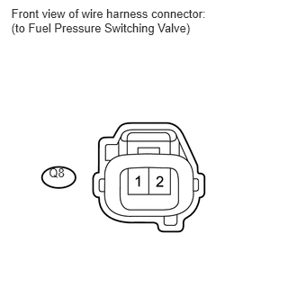
Disconnect the fuel pressure switching valve connector.
Connect the Techstream to the DLC3.
Enter the following menus: Powertrain / Engine and ECT / Active Test / Activate the Fuel Pressure Switching Valve.
Operate the fuel pressure switching valve.
Measure the voltage according to the value(s) in the table below.
- Standard Voltage:
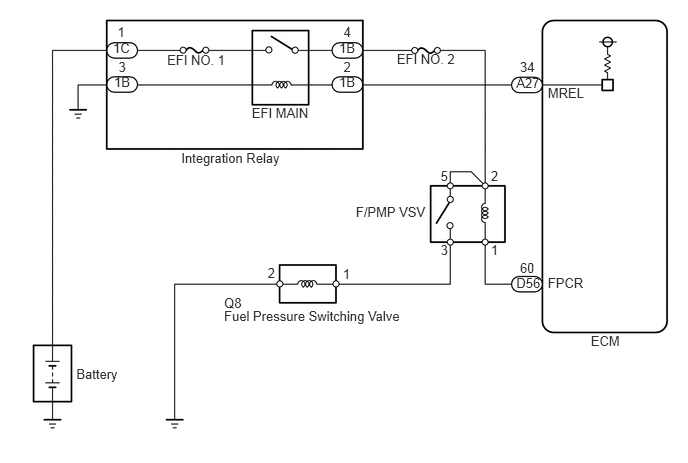
Tester Connection Condition Specified Condition R8-1 - R8-2 High selected in Active Test 11 to 14 V
OK
NG
Inspect the fuel pressure switching valve (See page Engine / Hybrid System>3UR-FBE FUEL>FUEL PRESSURE SWITCHING VALVE>INSPECTION).
- HINT:
-
Perform "Inspection After Repair" after replacing the fuel pump (See page Engine / Hybrid System>3UR-FBE ENGINE CONTROL>SFI SYSTEM>INITIALIZATION).
OK
NG
Inspect the F/PMP VSV relay (See page Engine / Hybrid System>3UR-FBE ENGINE CONTROL>RELAY>ON-VEHICLE INSPECTION).
OK
NG
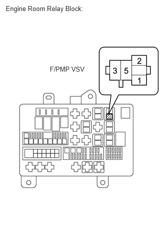
Remove the fuel pressure control valve relay (F/PMP VSV) from the engine room relay block.
Turn the ignition switch to ON.
Measure the voltage according to the value(s) in the table below.
- Standard Voltage:
Tester Connection Condition Specified Condition F/PMP VSV relay (5) - Body ground Ignition switch ON 11 to 14 V
OK
NG
Disconnect the fuel pressure switching valve connector.
Remove the fuel pressure control valve relay (F/PMP VSV) from the engine room relay block.
Measure the resistance according to the value(s) in the table below.
- Standard Resistance:
Tester Connection Condition Specified Condition Q8-1 - F/PMP VSV relay (3) Always Below 1 Ω Q8-2 - Body ground Always Below 1 Ω Q8-1 or F/PMP VSV relay (3) - Body ground Always 10 kΩ or higher
- HINT:
-
Perform "Inspection After Repair" after replacing the fuel pump (See page Engine / Hybrid System>3UR-FBE ENGINE CONTROL>SFI SYSTEM>INITIALIZATION).
OK
NG