Home › Engine / Hybrid System › 3UR-FE ENGINE CONTROL › SFI SYSTEM
RM27L0U _51 Engine / Hybrid System _049294 3UR-FE ENGINE CONTROL _0235547 SFI SYSTEM J

3UR-FE ENGINE CONTROL  SFI SYSTEM  ACIS Control Circuit  


DESCRIPTION

This circuit opens and closes the Intake Air Control Valve (IACV) in response to the engine load in order to increase the intake efficiency (ACIS: Acoustic Control Induction System).
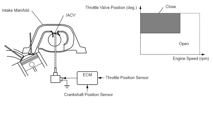
A165943E07
1.063,0.365 1.438,0.833 false 2.135,0.521 1.854,1.094 false 5.49,0.25 5.344,0.448 false 0.063,0.26 1.042,0.438 0.979,0.177 10 false Intake Manifold 2.219,0.427 2.667,0.625 0.448,0.198 10 false IACV 2.792,2.438 3.146,2.604 0.354,0.167 10 false ECM 3.552,2.531 5.073,2.698 1.521,0.167 10 false Throttle Position Sensor 2.156,3.104 3.885,3.271 1.729,0.167 10 false Crankshaft Position Sensor 5.573,0.135 5.969,0.302 0.396,0.167 10 false Close 6.021,1.385 6.438,1.563 0.417,0.177 10 false Open 2.865,0.167 4.698,0.354 1.833,0.188 10 false Throttle Valve Position (deg.) 5.813,1.885 7.094,2.083 1.281,0.198 10 false Engine Speed (rpm)

WIRING DIAGRAM

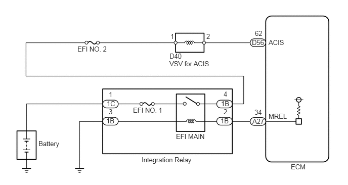
A164741E13
5.99,3.354 6.344,3.542 0.354,0.188 10 false ECM 5.531,0.792 5.896,0.958 0.365,0.167 10 false ACIS 5.531,2.313 5.979,2.5 0.448,0.188 10 false MREL 5.25,0.604 5.438,0.76 0.188,0.156 10 false 62 5.188,0.792 5.521,0.969 0.333,0.177 10 false D56 5.24,2.229 5.438,2.385 0.198,0.156 10 false 34 5.198,2.417 5.479,2.583 0.281,0.167 10 false A27 3.49,1.073 3.781,1.24 0.292,0.167 10 false D40 3.49,1.229 4.385,1.396 0.896,0.167 10 false VSV for ACIS 4.25,0.667 4.354,0.833 0.104,0.167 10 false 2 3.51,0.667 3.615,0.833 0.104,0.167 10 false 1 1.594,0.927 2.292,1.115 0.698,0.188 10 false EFI NO. 2 2.74,2.188 3.396,2.354 0.656,0.167 10 false EFI NO. 1 3.625,2.729 4.25,2.896 0.625,0.167 10 false EFI MAIN 2.917,3.208 4,3.385 1.083,0.177 10 false Integration Relay 4.542,2.406 4.781,2.563 0.24,0.156 10 false 1B 4.552,2.052 4.771,2.208 0.219,0.156 10 false 1B 4.604,2.219 4.719,2.385 0.115,0.167 10 false 2 4.604,1.854 4.719,2.021 0.115,0.167 10 false 4 2.188,2.406 2.406,2.563 0.219,0.156 10 false 1B 2.24,2.219 2.354,2.385 0.115,0.167 10 false 3 2.198,2.052 2.448,2.208 0.25,0.156 10 false 1C 2.24,1.865 2.344,2.021 0.104,0.156 10 false 1 0.792,2.875 1.26,3.052 0.469,0.177 10 false Battery

PROCEDURE

1.PERFORM ACTIVE TEST USING TECHSTREAM (OPERATE VSV FOR ACIS)
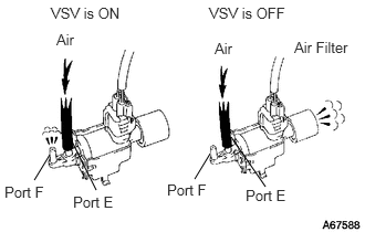
A067588E26
0.469,1.458 0.323,1.698 false 0.667,1.313 0.906,1.792 false 1.979,1.448 1.833,1.688 false 2.177,1.292 2.5,1.76 false 0.479,0.042 1.438,0.25 0.958,0.208 10 false VSV is ON 1.969,0.042 3.063,0.25 1.094,0.208 10 false VSV is OFF 0.531,0.292 0.917,0.49 0.385,0.198 10 false Air 2.021,0.375 2.354,0.573 0.333,0.198 10 false Air 2.771,0.365 3.375,0.573 0.604,0.208 10 false Air Filter 2.313,1.76 2.844,1.969 0.531,0.208 10 false Port E 1.573,1.708 2.094,1.917 0.521,0.208 10 false Port F 0.688,1.823 1.24,2.021 0.552,0.198 10 false Port E 0.042,1.729 0.542,1.917 0.5,0.188 10 false Port F

a.

Disconnect the vacuum hose from port F on the vacuum switching valve (for ACIS).


b.

Connect the Techstream to the DLC3.


c.

Start the engine.


d.

Enter the following menus: Powertrain / Engine and ECT / Active Test / Active the VSV for Intake Control.


e.

Operate the VSV for ACIS.


f.

Check the VSV air flow when switching the VSV.

OK:
Test Condition Specified Condition
VSV is ON Air from port E flows out through port F
VSV is OFF Air from port E flows out through air filter


OK

2.CHECK VACUUM HOSES (VACUUM SWITCHING VALVE - INTAKE AIR CONTROL VALVE, INTAKE MANIFOLD)

NG

4.INSPECT VACUUM SWITCHING VALVE
2.CHECK VACUUM HOSES (VACUUM SWITCHING VALVE - INTAKE AIR CONTROL VALVE, INTAKE MANIFOLD)

OK

3.INSPECT INTAKE MANIFOLD (INTAKE AIR CONTROL VALVE)

NG

REPAIR OR REPLACE VACUUM HOSES

3.INSPECT INTAKE MANIFOLD (INTAKE AIR CONTROL VALVE)

OK

PROCEED TO NEXT CIRCUIT INSPECTION SHOWN IN PROBLEM SYMPTOMS TABLE

NG

4.INSPECT VACUUM SWITCHING VALVE

OK

5.CHECK HARNESS AND CONNECTOR (VACUUM SWITCHING VALVE - ECM AND INTEGRATION RELAY)

NG

5.CHECK HARNESS AND CONNECTOR (VACUUM SWITCHING VALVE - ECM AND INTEGRATION RELAY)
a.

Remove the EFI NO. 2 fuse from the engine room relay block.


b.

Check the EFI NO. 2 fuse.


c.

Measure the resistance according to the value(s) in the table below.

Standard resistance:
Tester Connection Condition Specified Condition
EFI NO. 2 fuse Always Below 1 Ω


d.

Reinstall the EFI NO. 2 fuse.


e.

Disconnect the D40 intake air control valve connector.


f.

Disconnect the D56 ECM connector.


g.

Remove the integration relay from the engine room relay block.


h.

Disconnect the 1B integration relay connector.


i.

Measure the resistance according to the value(s) in the table below.

Standard resistance:
Tester Connection Condition Specified Condition
D40-2 - D56-62 (ACIS) Always Below 1 Ω
D40-1 - 1B-4 Always Below 1 Ω
D40-2 or D56-62 (ACIS) - Body ground Always 10 kΩ or higher
D40-1 or 1B-4 - Body ground Always 10 kΩ or higher


OK

NG

REPAIR OR REPLACE HARNESS OR CONNECTOR