Home › Engine / Hybrid System › CRUISE CONTROL › CRUISE CONTROL SYSTEM
RM27L0U _51 Engine / Hybrid System _049309 CRUISE CONTROL _0235639 CRUISE CONTROL SYSTEM C

CRUISE CONTROL  CRUISE CONTROL SYSTEM  C1267  Brake Pedal Load Sensing Switch  


DESCRIPTION

The skid control ECU receive signals from the active brake booster's internal micro switch to detect if the brake pedal is depressed.

DTC No. DTC Detection Condition Trouble Area
C1267 During cruise control operation a micro switch error is stored under the following conditions: A micro switch error flag remains ON for 0.5 seconds or more, the micro switch condition does not match the signal sent from the VSC system, or the micro switch and oil pressure sensor values do not match for 1 second or more.
·

Active brake booster (micro switch)

·

ECM

·

VSC system

·

Wire harness or connector


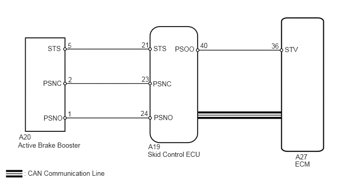
WIRING DIAGRAM

E345232E01
0.49,3.448 4.156,3.646 3.667,0.198 10 false : CAN Communication Line 0.385,2.708 0.844,2.906 0.458,0.198 10 false A20 0.365,2.875 3.427,3.073 3.063,0.198 10 false Active Brake Booster 3.01,2.906 3.469,3.104 0.458,0.198 10 false A19 3,3.063 5.448,3.26 2.448,0.198 10 false Skid Control ECU 6,3.115 6.458,3.313 0.458,0.198 10 false A27 5.99,3.26 6.448,3.458 0.458,0.198 10 false ECM 0.969,0.906 1.427,1.104 0.458,0.198 10 false STS 0.875,1.615 1.49,1.813 0.615,0.198 10 false PSNC 0.885,2.323 1.5,2.521 0.615,0.198 10 false PSNO 1.375,0.844 1.531,1.042 0.156,0.198 10 false 5 1.385,1.542 1.542,1.74 0.156,0.198 10 false 2 1.375,2.24 1.531,2.438 0.156,0.198 10 false 1 2.875,0.833 3.188,1.031 0.313,0.198 10 false 21 2.875,1.531 3.188,1.729 0.313,0.198 10 false 23 2.854,2.229 3.167,2.427 0.313,0.198 10 false 24 3.115,0.906 3.573,1.104 0.458,0.198 10 false STS 3.104,1.625 3.5,1.802 0.396,0.177 10 false PSNC 3.125,2.313 3.521,2.458 0.396,0.146 10 false PSNO 3.552,0.917 3.958,1.063 0.406,0.146 10 false PSOO 4.063,0.844 4.281,1.052 0.219,0.208 10 false 40 5.51,0.854 5.823,1.052 0.313,0.198 10 false 36 5.781,0.927 6.24,1.125 0.458,0.198 10 false STV

CAUTION / NOTICE / HINT

HINT:

This circuit uses CAN communication. Therefore, if there are any malfunctions in the communication circuit, one or more DTCs in the CAN communication system are output.


PROCEDURE

1.CHECK DTC (FOR VEHICLE STABILITY CONTROL SYSTEM)
a.

Check the DTC for Vehicle Stability Control System (See page Brake>BRAKE CONTROL / DYNAMIC CONTROL SYSTEMS>VEHICLE STABILITY CONTROL SYSTEM>DTC CHECK / CLEAR).

Result Proceed to
DTC is not output A
DTC is output B


A

2.CHECK HARNESS AND CONNECTOR (SKID CONTROL ECU - ECM)

B

2.CHECK HARNESS AND CONNECTOR (SKID CONTROL ECU - ECM)
a.

Disconnect the A27 connector from the ECM.
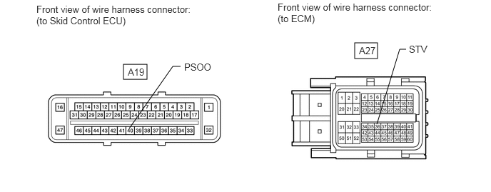

E345233E01
1.802,0.938 2.146,1.156 0.344,0.219 5.177,0.625 5.51,0.854 0.333,0.229 1.885,1.875 2.521,0.969 2.521,0.969 2.635,0.969 false 5.5,1.813 5.833,0.719 5.833,0.719 5.927,0.719 false 0.531,0.052 2.781,0.438 2.25,0.385 10 false Front view of wire harness connector: (to Skid Control ECU) 4.052,0.021 6.469,0.396 2.417,0.375 10 false Front view of wire harness connector: (to ECM) 2.688,0.896 3.302,1.094 0.615,0.198 10 false PSOO 1.865,0.969 2.323,1.167 0.458,0.198 10 false A19 5.969,0.635 6.427,0.833 0.458,0.198 10 false STV 5.24,0.656 5.698,0.854 0.458,0.198 10 false A27

b.

Disconnect the A19 connector from the ECU.


c.

Measure the resistance according to the value(s) in the table below.

Standard Resistance:
Tester Connection Condition Specified Condition
A19-40 (PSOO) - A27-36 (STV) Always Below 1 Ω
A19-40 (PSOO) or A27-36 (STV) - Body ground Always 10 kΩ or higher


d.

Reconnect the ECM and ECU connector.


OK

3.REPLACE VSC ACTUATOR ASSEMBLY

NG

REPAIR OR REPLACE HARNESS OR CONNECTOR

3.REPLACE VSC ACTUATOR ASSEMBLY
a.

Temporarily replace the VSC actuator assembly with a new or normally functioning one (See page Brake>BRAKE CONTROL / DYNAMIC CONTROL SYSTEMS>BRAKE ACTUATOR>REMOVAL).


NEXT

4.CLEAR DTC
4.CLEAR DTC

NEXT

5.CHECK FOR DTC
5.CHECK FOR DTC
a.

Check for DTC (See page Engine / Hybrid System>CRUISE CONTROL>CRUISE CONTROL SYSTEM>DTC CHECK / CLEAR).

OK:

C1267 is not output.


Result
Result Proceed to
OK A
NG (for 3UR-FE) B
NG (for 3UR-FBE) C


A

END (VSC ACTUATOR ASSEMBLY IS DEFECTIVE)

B

C