CRUISE CONTROL LASER SENSOR ADJUSTMENT
CAUTION / NOTICE / HINT
- CAUTION:
- ·
Do not stare at the luminous portion of the laser during adjustment. The intensity of the laser light is low, but it may result in loss of sight.
·If the operation is not carried out as specified, there may be a risk of exposure to hazardous radiation.
- HINT:
- ·
After replacing the ECM on vehicles with a dynamic laser cruise control system, it is necessary to initialize the ECM so that the ECM can recognize the dynamic laser cruise control system (See page Engine / Hybrid System>CRUISE CONTROL>DYNAMIC LASER CRUISE CONTROL SYSTEM>INITIALIZATION).
·After replacing the distance control ECU, it is necessary to initialize the distance control ECU so that the ECU can recognize the specification of the vehicle (See page Engine / Hybrid System>CRUISE CONTROL>DYNAMIC LASER CRUISE CONTROL SYSTEM>INITIALIZATION).
·There is a limitation on laser beam axis adjustment.
·Since the laser sensor is installed in the bumper reinforcement, it is important that the laser sensor, bumper reinforcement, and other related parts are installed properly.
·When the sensor is removed from the vehicle for trouble diagnosis or repair, it is necessary to adjust the laser beam axis after the operation.
PROCEDURE

 88211A
1.ADJUST LASER SENSOR
- NOTICE:
- ·
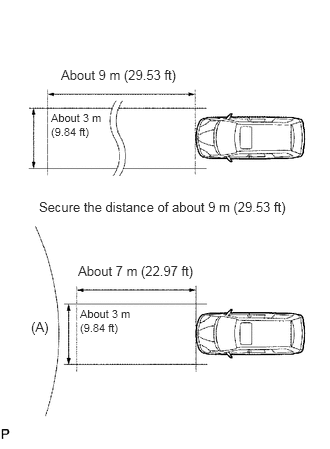
Perform measurement indoors on a level ground and in front of a blank wall. Park the vehicle at least 9 m (29.53 ft) from the wall. When performing adjustment outdoors, make sure that it is not raining or snowing.
·Check that there are no reflective materials in the surroundings or on the ground.
·If it is impossible to secure a distance of approximately 9 m (29.53 ft) in front of the vehicle, be sure to secure at least 7 m (22.97 ft) from the vehicle, and cover the area marked [A] with a black cloth. If not covered with a black cloth, the laser sensor may detect something other than the target and it will fail to adjust properly.
Preparation for adjusting the laser beam axis
Adjust the tires pressure properly (See page Suspension>TIRE / WHEEL>TIRE AND WHEEL SYSTEM>INSPECTION).
Luggage in the vehicle, such as in the trunk, should be unloaded.
Clean the light-emitting and light-receiving portions of the laser sensor.
Prepare a 10 m (32.81 ft) string, a string with a sharp-pointed weight (plumb bob), and a 5 m (16.41 ft) tape measure.
Reflector (SST) placement
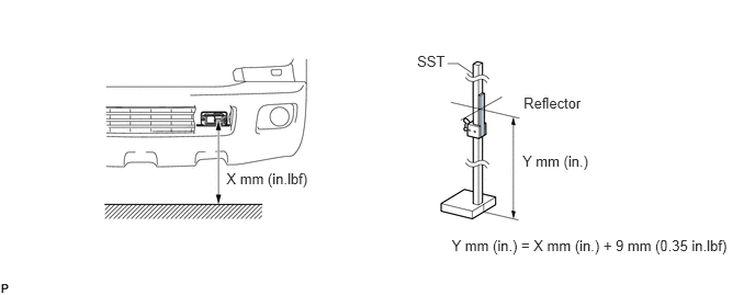
Measure the height to the center of the laser luminous portion.
Adjust the center height of the reflector 9 mm (0.35 in.) higher than the center of the luminous portion.
- SST
- 09870-60000
- NOTICE:
-
Adjust it as precise as possible.
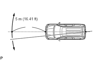
From the center (center of the emblem) of the front and rear bumpers, hang down the string with the plumb bob and mark the center points (both front and rear) of the vehicle on the ground.
Make a 5 m (16.41 ft) mark when the string and the front vehicle center mark intersect.
- HINT:
-
Fix one end of the string to the rear center mark and move the other end right and left at a point 5 m (16.41 ft) from the front of the vehicle.
From the 5 m (16.41 ft) marked position, measure 478 mm (18.8 in.) to the left and place the reflector there.
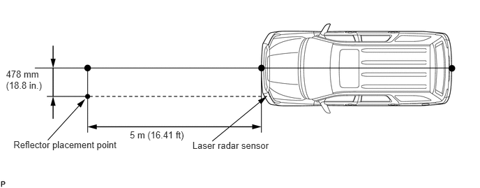
- NOTICE:
-
Perform it as precisely as possible.
Check L/C Option Flag in the Data List and when the result is YES, perform adjustment of the laser beam axis
(See page Engine / Hybrid System>CRUISE CONTROL>DYNAMIC LASER CRUISE CONTROL SYSTEM>DATA LIST / ACTIVE TEST)
Check L/C Option Flag in the Data List and when the result is NO, perform initialization using the following steps.
(See page Engine / Hybrid System>CRUISE CONTROL>DYNAMIC LASER CRUISE CONTROL SYSTEM>INITIALIZATION)
Turn the ignition switch to ON.
Turn the cruise main switch on.
With the brake pedal depressed, push the cruise control main switch to RES/ACC 3 times within 3 seconds. Check that the buzzer sounds at this time.
- NOTICE:
-
Do not turn the headlight dimmer switch on at this time because the optical axis automatic adjustment mode has already started, which may lead to an incorrect optical axis setting.
After performing initialization, check L/C Option Flag in the Data List again and when the result is YES, perform adjustment of the laser beam axis.
(See page Engine / Hybrid System>CRUISE CONTROL>DYNAMIC LASER CRUISE CONTROL SYSTEM>DATA LIST / ACTIVE TEST)
Adjustment of the laser beam axis
Connect the Techstream to the DLC3.
Turn the headlight dimmer switch off.
Turn the ignition switch to ON.
Turn the Techstream main switch on, and turn the cruise control main switch on.
Enter the following menus: Powertrain / Laser Cruise / Utility / Beam Axis Adjustment.
Follow the Techstream display, and continue with the adjustment.
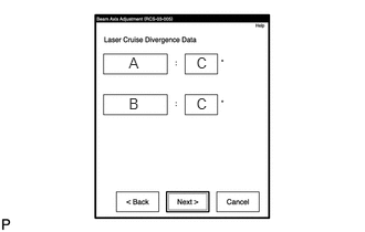
Confirm the current value of the laser beam (The default reading is 6.3° when the reflector position is out of range.)
- HINT:
- ·
Check that Upper Side or Lower Side is displayed in area A.
·Check that Left Side or Right Side is displayed in area B.
·Check that an angle value between 0.0 and 6.3 is displayed in area C.
Move the reflector either to the right or left by 500 mm (19.69 in.) and check that the value changes.
- NOTICE:
-
When the values do not change, it is possible that the direction of the laser radar sensor is greatly off target, and that the laser radar sensor is aiming at something different. Check the installation condition of the laser radar sensor.
Return the reflector to the original position and read the current angle.
- Standard:
Display Angle Upper/Lower Side Below 2.7° Right/Left Side Below 4.0°
- HINT:
- ·
If the values are within the auto adjustment range, proceed to step [*1].
·When the values displayed on the screen are normal, the values should be within the standard value ranges shown above. If any value is out of range, check the installation condition of the bumper reinforcement, etc. as the beam axis cannot be adjusted automatically.
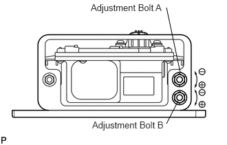
If the values are out of the auto axis adjustment range or the values are not displayed, it is not possible to operate Beam Axis Adjustment. In this case, mechanically adjust the direction of the radar sensor by adjustment bolts A and B to make the values within the standard value ranges.
- HINT:
-
Adjust the direction of the radar with adjustment bolts A and B until the values are within the auto axis adjustment range. Move the reflector from the default position as necessary (Upper/Lower, Right/Left) to find the reflector position where the current angle can be read using the Techstream. Adjust the direction of the reflector in the inverse of the direction moved by adjustment bolts A and B until the values are within the standard value ranges.
- Adjustment:
Adjust Direction Adjust Method Adjust Angle Upper Rotate adjustment bolt B in (+) direction 3/4 turn changes the angle 1° Lower Rotate adjustment bolt B in (-) direction 3/4 turn changes the angle 1° Left Rotate adjustment bolts A and B in (-) direction 4.5 turns changes the angle 1° Right Rotate adjustment bolts A and B in (+) direction 4.5 turns changes the angle 1°
Turn the headlight dimmer switch to the TAIL position.[*1]
Beam Axis Adjustment will be performed automatically.
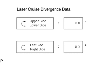
When the adjustment is completed, the Upper/Lower Side and Right/Left Side indicators show 0 and the system beeps for 10 seconds. During this time, Upper and Lower flash alternately on the screen, and Left and Right flash alternately on the screen.
- NOTICE:
-
Adjustment values are calculated and then stored in the laser sensor. Because the system is not controlled mechanically, the same value as before is displayed to adjust the beam axis.
Select "NEXT" on Techstream to complete the adjustment procedure.