BRAKE CONTROL / DYNAMIC CONTROL SYSTEMS VEHICLE STABILITY CONTROL SYSTEM C1231/31 Steering Angle Sensor Circuit Malfunction
DESCRIPTION
The steering angle sensor signal is sent to the skid control ECU via the CAN communication system. When there is a malfunction in the CAN communication system, it will be detected by the diagnostic function.
| DTC Code | DTC Detection Condition | Trouble Area |
|---|---|---|
| C1231/31 | When any of following conditions detected:
1.
The ECU-B1 fuse blows or the ignition switch is turned to ON with the ECU-B1 fuse removed. 2.
Skid control ECU receives abnormal signals from steering angle sensor. 3.
Skid control ECU receives abnormal voltage signals from steering angle sensor. 4.
Despite calibration being conducted by skid control ECU, it does not finish within 15 seconds. 5.
Abnormal difference between yaw rate and deceleration sensor and steering angle sensor signals continues for approximately 2 seconds or more during driving. |
·
ECU-B1 fuse ·
Steering angle sensor ·
Steering angle sensor circuit ·
Steering angle sensor power supply ·
CAN communication system ·
VSC actuator (skid control ECU) |
- HINT:
-
DTC C1231/31 is cleared automatically when the ignition switch is turned from off to ON after the voltage supply to the steering angle sensor returns to normal.
WIRING DIAGRAM
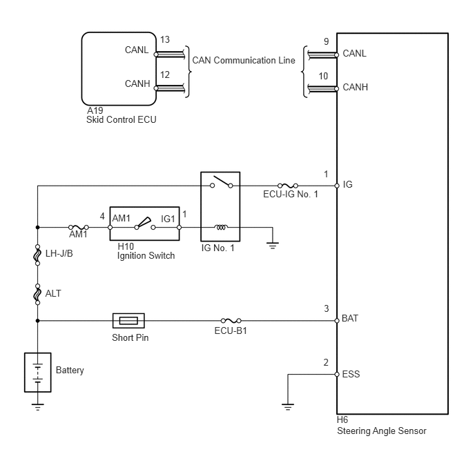
CAUTION / NOTICE / HINT
- HINT:
-
When U0073/94, U0123/62, U0124/69 or U0126/63 is output together with C1231/31, inspect and repair the trouble areas indicated by U0073/94, U0123/62, U0124/69 or U0126/63 first.
- NOTICE:
- ·
When replacing the VSC actuator assembly, perform zero point calibration (See page Brake>BRAKE CONTROL / DYNAMIC CONTROL SYSTEMS>VEHICLE STABILITY CONTROL SYSTEM>CALIBRATION).
·Inspect the fuses for circuits related to this system before performing the following inspection procedure.
PROCEDURE
Check that the steering wheel is in the centered position.
Disconnect the negative battery terminal for more than 2 seconds.
- NOTICE:
-
After the ignition switch is turned off, the navigation system requires approximately 90 seconds to record various types of memory and settings. As a result, after turning the ignition switch off, wait 90 seconds or more before disconnecting the cable from the negative (-) battery terminal.
Reconnect the negative battery terminal.
After driving the vehicle straight ahead at 15 km/h (9.3 mph) or more for a few seconds, drive the vehicle at a speed of 45 km/h (28 mph) or more and turn the steering wheel to the right and left for several seconds.
NEXT
Connect the Techstream to the DLC3.
Turn the ignition switch to ON.
Turn the Techstream ON.
Check that the steering wheel is centered.
Select the Data List mode on the Techstream.
Techstream
| Tester Display | Measurement Item/Range | Normal Condition | Diagnostic Note |
|---|---|---|---|
| Steering Angle Sensor | Steering angle sensor /
min.: -3276.8°, max.: 3276.7° |
- | Left turn: Increase
Right turn: Decrease |
| Steering Angle Value | Steering angle value /
min.: -3276.8°, max.: 3276.7° |
- | - |
Check that the steering wheel turning angle of the steering angle sensor changes when turning the steering wheel.
- OK:
Turning the steering wheel to the left: Value increases
Turning the steering wheel to the right: Value decreases
OK
NG
Clear the DTC (See page Brake>BRAKE CONTROL / DYNAMIC CONTROL SYSTEMS>VEHICLE STABILITY CONTROL SYSTEM>DTC CHECK / CLEAR).
Start the engine.
After driving the vehicle straight ahead at 15 km/h (9.3 mph) or more for a few seconds, drive the vehicle at a speed of 45 km/h (28 mph) or more and turn the steering wheel to the right and left for several seconds.
Check if the same DTC is recorded (See page Brake>BRAKE CONTROL / DYNAMIC CONTROL SYSTEMS>VEHICLE STABILITY CONTROL SYSTEM>DTC CHECK / CLEAR).
| Result | Proceed to |
|---|---|
| DTC is output | A |
| DTC is not output | B |
A
B
(See pageGeneral>INTRODUCTION>HOW TO TROUBLESHOOT ECU CONTROLLED SYSTEMS>HOW TO PROCEED WITH TROUBLESHOOTING)
Check if the CAN communication system DTC is output (See page Power Source / Network>NETWORKING>CAN COMMUNICATION SYSTEM>DIAGNOSIS SYSTEM).
| Result | Proceed to |
|---|---|
| DTC is not output | A |
| DTC is output | B |
A
B
(See pagePower Source / Network>NETWORKING>CAN COMMUNICATION SYSTEM>HOW TO PROCEED WITH TROUBLESHOOTING)
Check that the steering angle sensor has been installed correctly (See page Brake>BRAKE CONTROL / DYNAMIC CONTROL SYSTEMS>STEERING ANGLE SENSOR>INSTALLATION).
- OK:
The sensor is installed correctly.
OK
NG
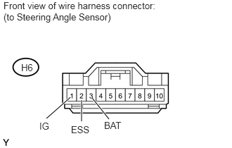
Remove the steering wheel and the column cover lower.
Disconnect the steering angle sensor connector.
Measure the voltage according to the value(s) in the table below.
- Standard Voltage:
Tester Connection Switch Condition Specified Condition H6-1(IG) - Body ground Ignition switch ON 11 to 14 V H6-3 (BAT) - Body ground Always
Measure the resistance according to the value(s) in the table below.
- Standard Resistance:
Tester Connection Condition Specified Condition H6-2 (ESS) - Body ground Always Below 1 Ω
OK
NG
Replace the steering angle sensor (See page Brake>BRAKE CONTROL / DYNAMIC CONTROL SYSTEMS>STEERING ANGLE SENSOR>REMOVAL).
NEXT
Clear the DTC (See page Brake>BRAKE CONTROL / DYNAMIC CONTROL SYSTEMS>VEHICLE STABILITY CONTROL SYSTEM>DTC CHECK / CLEAR).
Start the engine.
Drive the vehicle at a speed of 45 km/h (28 mph) or more and turn the steering wheel to the right and left for several seconds.
Check if the same DTC is recorded (See page Brake>BRAKE CONTROL / DYNAMIC CONTROL SYSTEMS>VEHICLE STABILITY CONTROL SYSTEM>DTC CHECK / CLEAR).
| Result | Proceed to |
|---|---|
| DTC is output | A |
| DTC is not output | B |
A
B