Home › Steering › STEERING COLUMN › POWER TILT AND POWER TELESCOPIC STEERING COLUMN SYSTEM
RM27L0U _55 Steering _049327 STEERING COLUMN _0235762 POWER TILT AND POWER TELESCOPIC STEERING COLUMN SYSTEM C

STEERING COLUMN  POWER TILT AND POWER TELESCOPIC STEERING COLUMN SYSTEM  B2603  Tilt and Telescopic Manual Switch Circuit Malfunction  


DESCRIPTION

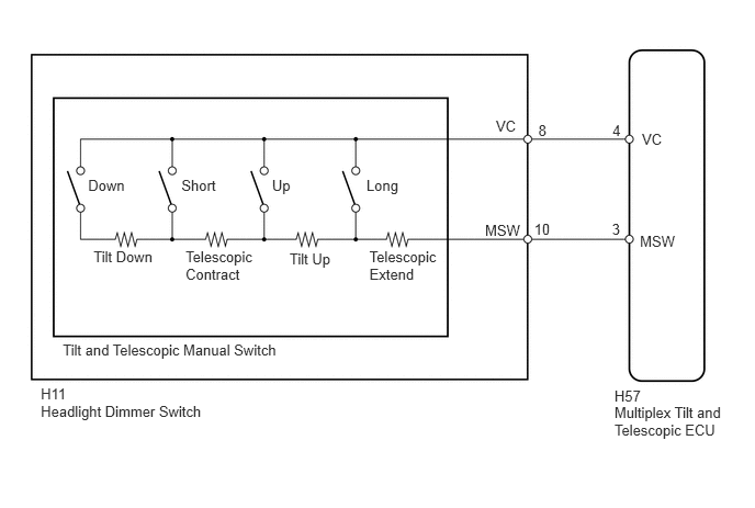
Different voltage values are input to the multiplex tilt and telescopic ECU by operating the tilt and telescopic manual switch. The multiplex tilt and telescopic ECU then judges which motor and in which direction that motor should be moved based on the voltage value.

DTC Code Detection Condition Trouble Area
B2603 When operating the tilt and telescopic manual switch, an abnormal voltage value is input to the multiplex tilt and telescopic ECU.
·

Tilt and telescopic manual switch

·

Tilt and telescopic manual switch circuit

·

Multiplex tilt and telescopic ECU


WIRING DIAGRAM

C159015E03
5.832,3.836 6.939,4.149 1.107,0.313 10 Multiplex Tilt and Telescopic ECU 0.387,3.824 2.691,4.017 2.304,0.193 10 Headlight Dimmer Switch 0.595,3.243 2.718,3.403 2.123,0.161 10 Tilt and Telescopic Manual Switch 4.604,2.103 4.973,2.257 0.368,0.154 10 MSW 4.707,1.118 4.927,1.274 0.220,0.156 10 VC 6.074,2.206 6.442,2.360 0.368,0.154 10 MSW 6.093,1.241 6.313,1.398 0.220,0.156 10 VC 3.478,1.673 3.883,1.865 0.405,0.192 10 Long 2.582,1.673 2.867,1.865 0.285,0.192 10 Up 1.722,1.673 2.128,1.865 0.405,0.192 10 Short 0.836,1.673 1.241,1.865 0.405,0.192 10 Down 0.887,2.356 1.508,2.503 0.621,0.147 10 Tilt Down 1.761,2.356 2.443,2.673 0.682,0.317 10 Telescopic Contract 2.748,2.377 3.171,2.529 0.423,0.152 10 Tilt Up 3.506,2.356 4.194,2.704 0.687,0.348 10 Telescopic Extend 5.07,2.098 5.245,2.264 0.174,0.165 10 10 5.11,1.157 5.284,1.322 0.174,0.165 10 8 5.813,1.157 5.987,1.322 0.174,0.165 10 4 5.809,2.098 5.983,2.264 0.174,0.165 10 3 5.832,3.675 6.136,3.850 0.304,0.174 10 H57 0.387,3.661 0.691,3.836 0.304,0.174 10 H11

PROCEDURE

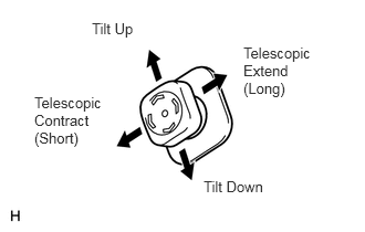
1.READ VALUE USING TECHSTREAM (TILT AND TELESCOPIC MANUAL SWITCH)
C113518E10
0.865,0.188 1.313,0.385 0.448,0.198 10 false Tilt Up 1.917,1.677 2.604,1.875 0.688,0.198 10 false Tilt Down 2.292,0.417 2.99,0.938 0.698,0.521 10 false Telescopic Extend (Long) 0.323,0.885 1.021,1.406 0.698,0.521 10 false Telescopic Contract (Short)

a.

Use the Data List to check if the tilt and telescopic manual switch is functioning properly.

Tilt & Telescopic
Tester Display Measurement Item/Range Normal Condition Diagnostic Note
T&T Manual SW Data Voltage data of manual switch / min.: 0.00 V, max.: 4.99 V Neutral position: Below 0.2 V
Tilt up: 1.67 to 2.13 V
Tilt down: 0.54 to 0.74 V
Telescopic contract: 1.08 to 1.40 V
Telescopic extend: 2.22 to 2.77 V
-


Result
Result Proceed to
Switch voltages in all directions are outside the standard. A
Switch voltages in certain directions are outside the standard. B
Switch voltages in all directions are within the standard. C


A

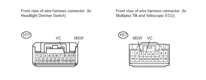
2.CHECK HARNESS AND CONNECTOR (MULTIPLEX TILT AND TELESCOPIC ECU - HEADLIGHT DIMMER SWITCH)

B

REPLACE HEADLIGHT DIMMER SWITCH

C

2.CHECK HARNESS AND CONNECTOR (MULTIPLEX TILT AND TELESCOPIC ECU - HEADLIGHT DIMMER SWITCH)
U153463E01
4.031,0.296 6.518,0.767 2.487,0.471 10 Front view of wire harness connector: (to Multiplex Tilt and Telescopic ECU) 2.576,1.249 2.937,1.450 0.361,0.201 10 MSW 1.941,1.249 2.256,1.450 0.315,0.201 10 VC 4.167,1.136 4.477,1.337 0.310,0.201 10 H57 0.804,1.137 1.100,1.338 0.296,0.201 10 H11 0.726,0.296 3.213,0.767 2.486,0.471 10 Front view of wire harness connector: (to Headlight Dimmer Switch) 2.749,1.434 2.551,1.902 false 2.061,1.434 2.259,1.902 false 4.616,1.249 4.978,1.450 0.361,0.201 10 MSW 5.115,1.249 5.430,1.450 0.315,0.201 10 VC 5.201,1.434 5.073,1.846 false 4.793,1.434 4.921,1.846 false

a.

Disconnect the H57 multiplex tilt and telescopic ECU connector.


b.

Disconnect the H11 headlight dimmer switch connector.


c.

Measure the resistance according to the value(s) in the table below.

Standard Resistance:
Tester Connection Condition Specified Condition
H57-4 (VC) - H11-8 (VC) Always Below 1 Ω
H57-3 (MSW) - H11-10 (MSW) Always Below 1 Ω
H11-8 (VC) - Body ground Always 10 kΩ or higher
H11-10 (MSW) - Body ground Always 10 kΩ or higher


OK

3.INSPECT MULTIPLEX TILT AND TELESCOPIC ECU (VC TERMINAL VOLTAGE)

NG

REPAIR OR REPLACE HARNESS OR CONNECTOR

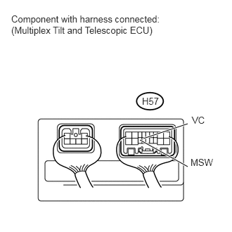
3.INSPECT MULTIPLEX TILT AND TELESCOPIC ECU (VC TERMINAL VOLTAGE)
a.
U153418E02
2.073,2.073 2.781,2.469 true 2.125,2.052 2.781,1.833 true 2.844,1.698 3.094,1.896 0.25,0.198 10 false VC 2.823,2.323 3.188,2.521 0.365,0.198 10 false MSW 2.104,1.417 2.396,1.615 0.292,0.198 10 false H57 0.167,0.198 2.656,0.594 2.49,0.396 10 false Component with harness connected: (Multiplex Tilt and Telescopic ECU)

Reconnect the H57 multiplex tilt and telescopic ECU connector.


b.

Measure the voltage according to the value(s) in the table below.

Standard Voltage:
Tester Connection Switch Condition Specified Condition
H57-4 (VC) - H57-3 (MSW) Ignition switch ON 4.9 to 5.1 V


OK

4.INSPECT HEADLIGHT DIMMER SWITCH (TILT AND TELESCOPIC MANUAL SWITCH)

NG

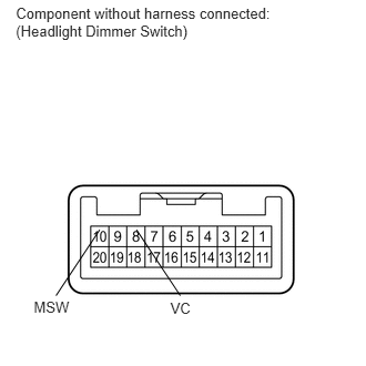
4.INSPECT HEADLIGHT DIMMER SWITCH (TILT AND TELESCOPIC MANUAL SWITCH)
a.
C160341E04
0.149,0.047 2.685,0.566 2.536,0.519 10 Component without harness connected: (Headlight Dimmer Switch) 1.6,2.816 1.895,3.062 0.295,0.246 10 VC 0.317,2.799 0.778,3.038 0.461,0.239 10 MSW 0.526,2.776 0.936,2.158 false 1.693,2.776 1.282,2.158 false

Disconnect the H11 headlight dimmer switch connector.


b.

Measure the resistance according to the value(s) in the table below.

Standard Resistance:
Tester Connection Switch Condition Specified Condition
8 (VC) - 10 (MSW) Tilt up 360 Ω
Tilt down 1990 Ω
Telescopic contract 790 Ω
Telescopic extend 160 Ω


OK

NG

REPLACE HEADLIGHT DIMMER SWITCH