Home › Vehicle Exterior › MIRROR (EXT) › POWER MIRROR CONTROL SYSTEM(w/ Memory)
RM27L0U _59 Vehicle Exterior _049350 MIRROR (EXT) _0235974 POWER MIRROR CONTROL SYSTEM(w/ Memory) J

MIRROR (EXT)  POWER MIRROR CONTROL SYSTEM(w/ Memory)  Reverse Shift-linked Function of Power Mirrors does not Operate  


SYSTEM DESCRIPTION

When the reverse signal is sent from the ECM through the CAN communication line to the outer mirror control ECU, the outer mirror control ECU activates the outer rear view mirror LH and RH reverse shift-linked function.

HINT:

The reverse shift-linked function will not occur when the outer mirror reverse gear link switch is not ON.


WIRING DIAGRAM
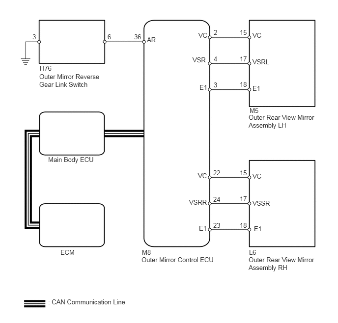
B193748E05
5.281,5.271 5.479,5.448 0.198,0.177 10 false L6 3.01,5.271 3.24,5.458 0.229,0.188 10 false M8 1.021,6.323 2.729,6.51 1.708,0.188 10 false : CAN Communication Line 1.281,5.271 1.656,5.75 0.375,0.479 10 false ECM 0.844,1.365 1.146,1.552 0.302,0.188 10 false H76 5.292,2.26 5.542,2.448 0.25,0.188 10 false M5 5.354,1.792 5.583,1.948 0.229,0.156 10 false E1 5.354,1.229 5.75,1.385 0.396,0.156 10 false VSRL 5.354,0.667 5.583,0.823 0.229,0.156 10 false VC 4.229,1.771 4.427,1.927 0.198,0.156 10 false E1 4.083,1.188 4.417,1.344 0.333,0.156 10 false VSR 4.208,0.667 4.427,0.823 0.219,0.156 10 false VC 5.083,0.604 5.271,0.76 0.188,0.156 10 false 15 5.083,1.167 5.26,1.323 0.177,0.156 10 false 17 5.083,1.708 5.26,1.865 0.177,0.156 10 false 18 4.531,0.604 4.635,0.76 0.104,0.156 10 false 2 4.531,1.167 4.635,1.323 0.104,0.156 10 false 4 4.531,1.719 4.635,1.875 0.104,0.156 10 false 3 5.385,4.771 5.615,4.927 0.229,0.156 10 false E1 5.354,4.229 5.75,4.385 0.396,0.156 10 false VSSR 5.354,3.656 5.583,3.813 0.229,0.156 10 false VC 4.219,4.76 4.417,4.917 0.198,0.156 10 false E1 4.01,4.208 4.458,4.365 0.448,0.156 10 false VSRR 4.198,3.646 4.427,3.802 0.229,0.156 10 false VC 5.083,3.583 5.26,3.74 0.177,0.156 10 false 15 5.083,4.698 5.26,4.854 0.177,0.156 10 false 18 5.083,4.135 5.26,4.292 0.177,0.156 10 false 17 4.521,3.583 4.708,3.74 0.188,0.156 10 false 22 4.521,4.146 4.708,4.302 0.188,0.156 10 false 24 4.521,4.698 4.698,4.854 0.177,0.156 10 false 23 1.021,3.302 2.052,3.813 1.031,0.51 10 false Main Body ECU 0.688,0.698 0.885,0.854 0.198,0.156 10 false 3 2.281,0.698 2.479,0.854 0.198,0.156 10 false 6 2.844,0.698 3.042,0.854 0.198,0.156 10 false 36 3.115,0.76 3.448,0.917 0.333,0.156 10 false AR 0.833,1.542 2.125,1.875 1.292,0.333 10 false Outer Mirror Reverse Gear Link Switch 5.271,2.406 6.667,2.75 1.396,0.344 10 false Outer Rear View Mirror Assembly LH 3,5.427 4.563,5.625 1.563,0.198 10 false Outer Mirror Control ECU 5.271,5.427 6.698,5.792 1.427,0.365 10 false Outer Rear View Mirror Assembly RH

PROCEDURE

1.CHECK DTC
a.

Use the Techstream to check if the CAN communication system is functioning normally (See page Power Source / Network>NETWORKING>CAN COMMUNICATION SYSTEM>DIAGNOSIS SYSTEM).

Result
Result Proceed to
CAN DTC is not output A
CAN DTC is output B


A

2.READ VALUE USING TECHSTREAM (PARK/NEUTRAL POSITION SWITCH)

B

2.READ VALUE USING TECHSTREAM (PARK/NEUTRAL POSITION SWITCH)
a.

Connect the Techstream to the DLC3.


b.

Turn the ignition switch to ON.


c.

Turn the Techstream ON.


d.

Enter the following menus: Powertrain / ECT / Data List.


e.

According to the display on the Techstream, read the Data List.

ECT
Tester Display Measurement Item/Display Normal Condition Diagnostic Note
Shift SW Status (R Range) PNP switch status / ON or OFF ON: Shift lever in R
OFF: Shift lever not in R
-

OK:

On the Techstream screen, each item changes between ON and OFF according to above chart.


Result
Result Proceed to
OK A
NG (AB60E automatic transmission) B
NG (AB60F automatic transmission) C


A

3.READ VALUE USING TECHSTREAM (MIRROR POSITION SENSOR)

B

GO TO AUTOMATIC TRANSMISSION SYSTEM (PNP SWITCH CIRCUIT)

C

GO TO AUTOMATIC TRANSMISSION SYSTEM (PNP SWITCH CIRCUIT)

3.READ VALUE USING TECHSTREAM (MIRROR POSITION SENSOR)
a.

Connect the Techstream to the DLC3.


b.

Turn the ignition switch to ON.


c.

Turn the Techstream ON.


d.

Enter the following menus: Body Electrical / Mirror / Data List.


e.

According to the display on the Techstream, read the Data List.

Mirror
Tester Display Measurement Item/Display Normal Condition Diagnostic Note
RH Mir Position Sensor V RH side mirror vertical sensor voltage / MIN: 0 V, MAX: 5 V Within range from 0 to 5 V -
LH Mir Position Sensor V LH side mirror vertical sensor voltage / MIN: 0 V, MAX: 5 V Within range from 0 to 5 V -

OK:

When mirror control switch is operated to turn mirror upward or downward, voltage changes within range shown in above chart.


Result
Result Proceed to
Neither mirror operates normally A
LH side mirror does not operate normally B
RH side mirror does not operate normally C
Mirror operates normally D


A

4.INSPECT OUTER MIRROR REVERSE GEAR LINK SWITCH

B

6.CHECK OUTER MIRROR CONTROL ECU

C

8.CHECK OUTER MIRROR CONTROL ECU

D

REPLACE OUTER MIRROR CONTROL ECU

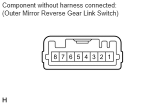
4.INSPECT OUTER MIRROR REVERSE GEAR LINK SWITCH
a.
C155488E04
0.044,0.018 2.552,0.331 2.508,0.313 10 Component without harness connected: (Outer Mirror Reverse Gear Link Switch)

Remove the switch.


b.

Measure the resistance according to the value(s) in the table below.

Standard Resistance:
Tester Connection Switch Condition Specified Condition
3 - 6 Pressed Below 1 Ω
Not pressed 10 kΩ or higher


OK

5.CHECK HARNESS AND CONNECTOR (OUTER MIRROR SWITCH - OUTER MIRROR CONTROL ECU)

NG

REPLACE OUTER MIRROR REVERSE GEAR LINK SWITCH

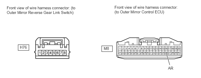
5.CHECK HARNESS AND CONNECTOR (OUTER MIRROR SWITCH - OUTER MIRROR CONTROL ECU)
a.

Disconnect the M8 ECU connector.

B443124E01
0.646,1.604 1.031,1.813 0.385,0.208 3.625,1.646 4.01,1.854 0.385,0.208 6.052,2.333 5.927,1.906 true 0.24,0.198 2.698,0.573 2.458,0.375 10 false Front view of wire harness connector: (to Outer Mirror Reverse Gear Link Switch) 4.083,0.177 6.344,0.563 2.26,0.385 10 false Front view of wire harness connector: (to Outer Mirror Control ECU) 0.708,1.615 1.021,1.802 0.313,0.188 10 false H76 3.698,1.656 3.969,1.833 0.271,0.177 10 false M8 5.99,2.365 6.229,2.542 0.24,0.177 10 false AR


b.

Disconnect the H76 switch connector.


c.

Measure the resistance according to the value(s) in the table below.

Standard Resistance:
Tester Connection Condition Specified Condition
H76-3 - Body ground Always Below 1 Ω
M8-36 (AR) - H76-6 Always Below 1 Ω
M8-36 (AR) - Body ground Always 10 kΩ or higher


OK

REPLACE OUTER MIRROR CONTROL ECU

NG

REPAIR OR REPLACE HARNESS OR CONNECTOR

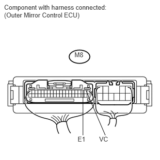
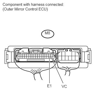
6.CHECK OUTER MIRROR CONTROL ECU
a.
U153276E01
0.089,0.07 2.375,0.448 2.286,0.378 10 Component with harness connected: (Outer Mirror Control ECU) 1.6,1.093 1.828,1.257 0.228,0.164 10 M8 1.668,2.906 1.941,3.072 0.273,0.166 10 E1 2.131,2.906 2.424,3.072 0.292,0.166 10 VC 1.782,1.944 1.782,2.906 false 1.848,1.944 2.262,2.906 false

Measure the voltage according to the value(s) in the table below.

Standard Voltage:
Tester Connection Switch Condition Specified Condition
M8-2 (VC) - M8-3 (E1) Ignition switch ON 3.5 to 5.5 V


b.

Measure the resistance according to the value(s) in the table below.

Standard Resistance:
Tester Connection Condition Specified Condition
M8-3 (E1) - Body ground Always Below 1 Ω


OK

7.CHECK HARNESS AND CONNECTOR (OUTER REAR VIEW MIRROR LH - OUTER MIRROR CONTROL ECU)

NG

REPLACE OUTER MIRROR CONTROL ECU

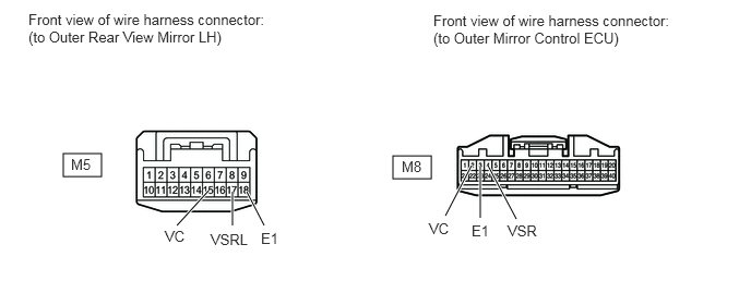
7.CHECK HARNESS AND CONNECTOR (OUTER REAR VIEW MIRROR LH - OUTER MIRROR CONTROL ECU)
a.

Disconnect the M8 ECU connector.

B443121E05
0.604,1.469 0.969,1.688 0.365,0.219 3.75,1.49 4.115,1.708 0.365,0.219 1.688,2.156 1.99,1.823 true 2.219,2.156 2.219,1.833 true 2.521,2.156 2.354,1.833 true 4.927,2.094 4.656,1.583 true 4.583,2.083 4.583,1.594 true 4.25,2.063 4.5,1.583 true 0.271,0.104 2.531,0.479 2.26,0.375 10 false Front view of wire harness connector: (to Outer Rear View Mirror LH) 4.135,0.115 6.396,0.49 2.26,0.375 10 false Front view of wire harness connector: (to Outer Mirror Control ECU) 3.833,1.51 4.073,1.698 0.24,0.188 10 false M8 0.677,1.49 0.917,1.677 0.24,0.188 10 false M5 2.01,2.208 2.385,2.385 0.375,0.177 10 false VSRL 1.573,2.177 1.813,2.365 0.24,0.188 10 false VC 2.49,2.198 2.729,2.385 0.24,0.188 10 false E1 4.094,2.104 4.333,2.292 0.24,0.188 10 false VC 4.5,2.125 4.74,2.313 0.24,0.188 10 false E1 4.844,2.125 5.219,2.302 0.375,0.177 10 false VSR


b.

Disconnect the M5 mirror connector.


c.

Measure the resistance according to the value(s) in the table below.

Standard Resistance:
Tester Connection Condition Specified Condition
M5-15 (VC) - M8-2 (VC) Always Below 1 Ω
M5-15 (VC) - Body ground Always 10 kΩ or higher
M5-17 (VSRL) - M8-4 (VSR) Always Below 1 Ω
M5-17 (VSRL) - Body ground Always 10 kΩ or higher
M5-18 (E1) - M8-3 (E1) Always Below 1 Ω
M5-18 (E1) - Body ground Always 10 kΩ or higher


OK

REPLACE OUTER REAR VIEW MIRROR ASSEMBLY LH

NG

REPAIR OR REPLACE HARNESS OR CONNECTOR

8.CHECK OUTER MIRROR CONTROL ECU
a.
U153277E02
1.771,2.052 1.771,2.979 true 1.833,2.052 2.26,2.979 true 0.094,0.073 2.375,0.448 2.281,0.375 10 false Component with harness connected: (Outer Mirror Control ECU) 1.604,1.094 1.833,1.26 0.229,0.167 10 false M8 1.688,2.99 1.958,3.156 0.271,0.167 10 false E1 2.208,3.01 2.448,3.177 0.24,0.167 10 false VC

Measure the voltage according to the value(s) in the table below.

Standard Voltage:
Tester Connection Switch Condition Specified Condition
M8-22 (VC) - M8-23 (E1) Ignition switch ON 3.5 to 5.5 V


b.

Measure the resistance according to the value(s) in the table below.

Standard Resistance:
Tester Connection Condition Specified Condition
M8-23 (E1) - Body ground Always Below 1 Ω


OK

9.CHECK HARNESS AND CONNECTOR (OUTER REAR VIEW MIRROR RH - OUTER MIRROR CONTROL ECU)

NG

REPLACE OUTER MIRROR CONTROL ECU

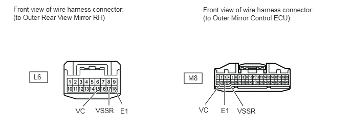
9.CHECK HARNESS AND CONNECTOR (OUTER REAR VIEW MIRROR RH - OUTER MIRROR CONTROL ECU)
a.

Disconnect the M8 ECU connector.

B443121E06
0.604,1.469 0.969,1.688 0.365,0.219 3.75,1.49 4.115,1.708 0.365,0.219 1.688,2.177 1.99,1.844 true 2.219,2.156 2.219,1.833 true 2.49,2.135 2.323,1.813 true 4.948,2.167 4.656,1.688 true 4.573,2.146 4.573,1.698 true 4.177,2.135 4.5,1.698 true 0.271,0.104 2.531,0.479 2.26,0.375 10 false Front view of wire harness connector: (to Outer Rear View Mirror RH) 4.135,0.115 6.396,0.49 2.26,0.375 10 false Front view of wire harness connector: (to Outer Mirror Control ECU) 3.833,1.51 4.073,1.698 0.24,0.188 10 false M8 0.688,1.49 0.927,1.677 0.24,0.188 10 false L6 1.948,2.177 2.344,2.365 0.396,0.188 10 false VSSR 1.542,2.188 1.781,2.375 0.24,0.188 10 false VC 2.448,2.188 2.688,2.375 0.24,0.188 10 false E1 4.052,2.167 4.292,2.354 0.24,0.188 10 false VC 4.5,2.177 4.74,2.365 0.24,0.188 10 false E1 4.833,2.188 5.229,2.375 0.396,0.188 10 false VSSR


b.

Disconnect the L6 mirror connector.


c.

Measure the resistance according to the value(s) in the table below.

Standard Resistance:
Tester Connection Condition Specified Condition
L6-15 (VC) - M8-22 (VC) Always Below 1 Ω
L6-15 (VC) - Body ground Always 10 kΩ or higher
L6-17 (VSSR) - M8-24 (VSRR) Always Below 1 Ω
L6-17 (VSSR) - Body ground Always 10 kΩ or higher
L6-18 (E1) - M8-23 (E1) Always Below 1 Ω
L6-18 (E1) - Body ground Always 10 kΩ or higher


OK

REPLACE OUTER REAR VIEW MIRROR ASSEMBLY RH

NG

REPAIR OR REPLACE HARNESS OR CONNECTOR