BRAKE (FRONT) FRONT BRAKE(for 4-Pot Caliper) INSTALLATION
CAUTION / NOTICE / HINT
- HINT:
- ·
Use the same procedure for the RH side and LH side.
·The following procedure is for the LH side.
PROCEDURE

 1.INSTALL FRONT DISC
- NOTICE:
- ·
Brake front discs must only be replaced in pairs (per axle).
·Fit new front discs only together with new front disc brake pads.
Position front disc on front axle hub sub-assembly.
Replace 5 mm hexagon bolt.
Tighten the 5 mm hexagon bolt.
- Torque:
- 16 N*m (163 kgf*cm, 12 ft.*lbf)
2.INSTALL FRONT DISC BRAKE CYLINDER ASSEMBLY
Install front disc brake cylinder assembly.
Replace E16 bolts.
Tighten the E16 bolts.
- Torque:
- 80 N*m (816 kgf*cm, 59 ft.*lbf)
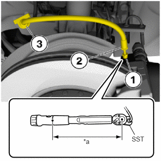
| *a | Torque Wrench Fulcrum Length |
Position front flexible hose (1) on the front disc brake cylinder assembly.
- NOTICE:
-
Make sure that the front flexible hose (1) does not rest against the components fixed to the body and that it is not twisted.
- HINT:
-
Schematic diagram is for example pur poses. Some parts may differ in certain details.
Tighten 11 mm union nut of the front flexible hose (1) on the front disc brake cylinder assembly; if necessary counter-hold at the knurling (2).
- SST
- 09700-WA070
- Torque:
- Specified tightening torque : 17 N*m (173 kgf*cm, 13 ft.*lbf)
- HINT:
-
Calculate the torque wrench reading when changing the fulcrum length of the torque wrench.
-
Click hereGeneral>INTRODUCTION>REPAIR INSTRUCTION>PRECAUTION
3.INSTALL FRONT DISC BRAKE PAD
4.INSTALL PAD WEAR INDICATOR WIRE LH
5.BLEED BRAKE LINE
6.INSTALL FRONT WHEEL
7.INSPECT FRONT BRAKE
- NOTICE:
- ·
When exchanging brake pads, reset the CBS display in accordance with factory specification (CBS reset).
·Carry out test braking while driving at low speed because the effectiveness of the brakes may be reduced during the initial braking operations.
·Exaggerated emergency and continuous braking operations for faster bedding-in are not permitted.
·Advise the customer not to perform intentional emergency braking operations for the first 200 km (124 mile) after the brakes have been replaced.
Fully depress brake pedal several times so that front disc brake pads contact front discs.
Adjust the brake fluid level to the maximum mark.
Perform a functional check on the brake test stand to ensure compliance of the brake system with statutory guidelines.
Attach mirror tag to inside mirror.
8. PERFORM CBS RESET