HEATING / AIR CONDITIONING B58 COMPRESSOR INSTALLATION
PROCEDURE

 1.ADJUST COMPRESSOR OIL (for Type A)
- NOTICE:
- ·
A new compressor with pulley assembly is filled with compressor oil at the factory. The amount of compressor oil in a new compressor with pulley assembly corresponds to the amount of compressor oil for the entire new and unfilled refrigerant circuit.
·When the compressor with pulley assembly is replaced, it is essential to adapt the amount of compressor oil.
- HINT:
- ·
The following procedure only applies when a new compressor with pulley assembly has a label with the amount of compressor oil.
·The compressor oil amount specification is located on the label on the compressor with pulley assembly.
·The position of the label can vary depending on the compressor with pulley assembly.
·The compressor oil specification on the label is in g, ml or cc. The cc are specified throughout these repair instructions for adjusting the amount of compressor oil, as g and ml closely correspond to cc.
Click hereVehicle Interior>HEATING / AIR CONDITIONING>B48 COMPRESSOR>INSTALLATION
2.ADJUST COMPRESSOR OIL (for Type B)
- NOTICE:
- ·
A new compressor with pulley assembly is filled with compressor oil at the factory. The amount of compressor oil in a new compressor with pulley assembly corresponds to the amount of compressor oil for the entire new and unfilled refrigerant circuit.
·When the compressor with pulley assembly is replaced, it is essential to adapt the amount of compressor oil.
- HINT:
-
The following procedure only applies if a new compressor with pulley assembly has a label indicating the amount of compressor oil.
Click hereVehicle Interior>HEATING / AIR CONDITIONING>B48 COMPRESSOR>INSTALLATION
3.INSTALL COMPRESSOR WITH PULLEY ASSEMBLY
Prepare for the installation of the compressor with pulley assembly.
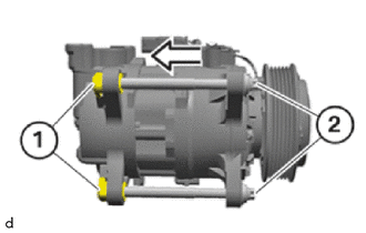
Install the E12 bolts (2) into the threaded support sleeve (1).
Slightly press back the threaded support sleeve (1) in the direction of the arrow with the E12 bolts (2).
Remove the E12 bolts (2) from the threaded support sleeve (1) again.
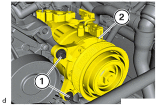
Install the compressor with pulley assembly (2) with the E12 bolts (1).
- Torque:
- 38 N*m (387 kgf*cm, 28 ft.*lbf)
Replace O-rings.
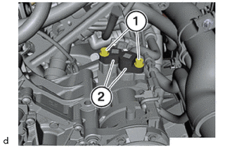
Install the suction pipe sub-assembly (2) with the T45 bolt (1).
- Torque:
- 19 N*m (194 kgf*cm, 14 ft.*lbf)
Install the discharge tube G (2) with the T45 bolt (1).
- Torque:
- 19 N*m (194 kgf*cm, 14 ft.*lbf)
Connect the connector.
4.INSTALL GENERATOR ASSEMBLY
16360A
5.INSTALL FAN WITH MOTOR ASSEMBLY
6. CHARGE AIR CONDITIONING SYSTEM WITH REFRIGERANT
7.WARM UP COMPRESSOR