INTERIOR PANELS / TRIM COMBINATION SWITCH(for Console Box) REMOVAL
CAUTION / NOTICE / HINT
- CAUTION:
- ·
Working on 12 V vehicle electrical system.
Risk of short circuits! Risk of fire!
-Detach the cable from the negative (-) battery terminal.
- NOTICE:
- ·
Before performing work on electronic components, disconnect the cable from the negative (-) battery terminal to prevent damage to the electrical system or components.
·When disconnecting the cable, turn the START-STOP button (engine switch) and headlight switch off and loosen the cable nut completely. Perform these operations without twisting or prying on the cable. Then disconnect the cable.
·Clock settings, radio settings, audio system memory, DTCs and other data will be cleared when the cable is disconnected from the negative (-) battery terminal. Write down any necessary data before disconnecting the cable.
- HINT:
- ·
Use the same procedure for LHD and RHD vehicles.
·The following procedure is for LHD vehicles.
PROCEDURE

 1.DISCONNECT CABLE FROM NEGATIVE BATTERY TERMINAL
for B48:
Click hereGeneral>MAINTENANCE>B48 BATTERY>REMOVAL
for B58:
Click hereGeneral>MAINTENANCE>B58 BATTERY>REMOVAL
58920C
2.REMOVE FRONT CONSOLE ARMREST ASSEMBLY
58822
3.REMOVE CONSOLE SIDE PANEL
4.REMOVE CONSOLE PANEL AND CONSOLE PANEL RETAINER
55432B
5.REMOVE INSTRUMENT PANEL FINISH LOWER PANEL
58818A
6.REMOVE FRONT CONSOLE BOX COVER
58804A
7.REMOVE UPPER CONSOLE PANEL SUB-ASSEMBLY
84720J
8.REMOVE PATTERN SELECT SWITCH ASSEMBLY
- NOTICE:
- ·
Electrostatic discharge.
Damage to or destruction of electrical components.
-Leave electrical components in original packaging until just before they are installed. Use the original packaging only for any return shipments. Always package removed components straight away.
-Only touch the housings of electrical components. Do not touch pins or multi-pin connectors directly.
-Antistatic work clothing and antistatic shoes (with ESD symbol).
-For additional information see:
Click hereGeneral>INTRODUCTION>REPAIR INSTRUCTION>PRECAUTION
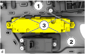
Loosen T20 screws (1).
Detach the claws (3).
Remove the pattern select switch assembly (2).