FRONT SUSPENSION FRONT UPPER SUSPENSION ARM INSTALLATION
CAUTION / NOTICE / HINT
- HINT:
- ·
Do not mix up the left and right.
·Use the same procedure for the RH side and LH side.
·The following procedure is for the LH side.
PROCEDURE

 48630
1.INSTALL FRONT UPPER SUSPENSION ARM ASSEMBLY
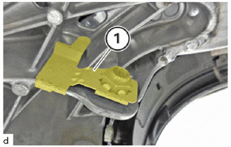
Replace the clip nut (1).
Position front upper suspension arm assembly at the front suspension crossmember sub-assembly.
Replace the 18 mm bolt.
w/ Front Suspension Member Bracket:
Position the front suspension member bracket sub-assembly and screw the 18 mm bolt in a few turns but do not tighten.
w/o Front Suspension Member Bracket:
Screw the 18 mm bolt in a few turns but do not tighten.
Position front upper suspension arm assembly on steering knuckle.
Replace nut.
Tighten the nut, if necessary, counter support the T40 "TORX" socket wrench.
- Torque:
- 175 N*m (1785 kgf*cm, 129 ft.*lbf)
Tighten 18 mm bolt.
- Torque:
- 100 N*m (1020 kgf*cm, 74 ft.*lbf)
- NOTICE:
-
Tighten the 18 mm bolt connection in the normal position.
Using SST, tighten the 18 mm bolt an additional 90°.
- SST
- 09900-WA010
- HINT:
- ·
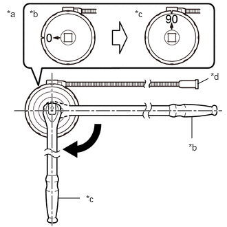 2.99,1.271 3.156,1.188 false 2.906,2.094 2.906,1.76 false 0.875,3 1.208,3 false 0.104,0.125 0.417,0.281 0.313,0.156 10 false *a 0.448,0.125 0.76,0.281 0.313,0.156 10 false *b 2.042,0.125 2.354,0.281 0.313,0.156 10 false *c 3.188,1.073 3.427,1.271 0.24,0.198 10 false *d 2.854,2.146 3.167,2.302 0.313,0.156 10 false *b 1.302,2.927 1.615,3.083 0.313,0.156 10 false *c
*a Example *b Before Tightening *c After Tightening *d Magnetic Portion
·The magnetic portion is used to secure the gauge to the vehicle.
·After first adjusting the needle of the gauge to 0°, tighten to the specified angle.
·Perform the work procedure carefully so that the gauge, etc. does not become tilted.
53896B
2.INSTALL FRONT FENDER SPLASH FRONT SHIELD
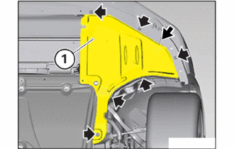
Insert the front fender splash front shield (1) at the side.
Tighten screws (arrows).
- Torque:
- 2.6 N*m (27 kgf*cm, 23 in.*lbf)
51410
3.INSTALL NO. 1 ENGINE UNDER COVER ASSEMBLY
53879
4.INSTALL FRONT FENDER LINER
5.INSTALL FRONT WHEEL
6.INSPECT AND ADJUST FRONT WHEEL ALIGNMENT