DOOR / HATCH BACK DOOR ADJUSTMENT
CAUTION / NOTICE / HINT
- CAUTION:
- ·
Shutting hood sub-assembly or back door panel sub-assembly.
Danger of injury!
-Support hood sub-assembly / back door panel sub-assembly in fully open position with the aid of a suitable device.
PROCEDURE

 67005
1.INSPECT BACK DOOR PANEL SUB-ASSEMBLY
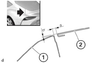
| (1) | Rear Side Panel |
| (2) | Back Door Panel Sub-assembly |
Check gap dimension of the rear side panel (1) for the back door panel sub-assembly (2).
- Gap dimension rear side panel to back door panel sub-assembly:
Area Measurement a 2.3 to 4.7 mm (0.091 to 0.185 in.) b -1.5 to 0.9 mm (-0.059 to 0.035 in.)
Gap dimension a does not correspond to the specifications.
Adjust back door panel sub-assembly on the back door hinge.
Dimension b does not correspond to the specifications.
Adjust the striker for the back door catch.
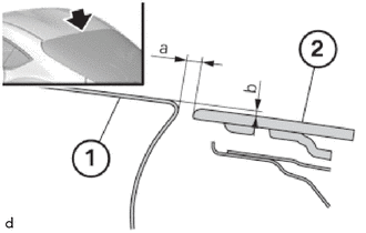
| (1) | Roof Outer Skin |
| (2) | Rear Window |
Check gap dimension of the roof outer skin (1) for the rear window (2).
- Gap dimension rear window to roof outer skin:
Area Measurement a 5.8 to 9.1 mm (0.228 to 0.358 in.) b 0.6 to 4.2 mm (0.024 to 0.165 in.)
Gap dimension a does not correspond to the specifications.
Adjust back door panel sub-assembly on the back door hinge.
Dimension b does not correspond to the specifications.
Adjust back door hinge to body.
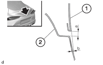
| (1) | Back Door Panel Sub-assembly |
| (2) | Rear Bumper Panel |
Check gap dimension of the back door panel sub-assembly (1) for the rear bumper panel (2).
- Gap dimension back door panel sub-assembly to rear bumper panel:
Area Measurement a 3.6 to 6.6 mm (0.142 to 0.260 in.) b 0.5 to 4.1 mm (0.020 to 0.161 in.)
Gap dimension a does not correspond to the specifications.
Gap dimension a does not correspond to the specifications.
Dimension b does not correspond to the specifications.
Adjust back door panel sub-assembly to back door hinge.
64330D
2.REMOVE PACKAGE TRAY TRIM PANEL ASSEMBLY
64711B
3.REMOVE DECK BOARD ASSEMBLY
81604
4.REMOVE TRIANGLE REFLECTOR SET
64716D
5.REMOVE DECK TRIM REAR COVER
67005
6.ADJUST BACK DOOR PANEL SUB-ASSEMBLY
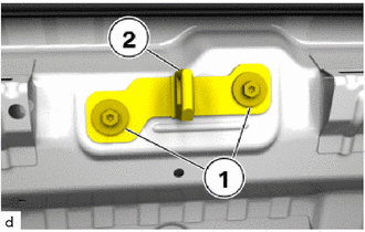
Loosen the 11 mm bolts (1) until the back door lock striker assembly for back door catch (2) can still be moved to the top and self-centers itself.
Close back door panel sub-assembly.
Open back door panel sub-assembly.
Tighten the 11 mm bolts (1).
- Torque:
- 19.0 N*m (194 kgf*cm, 14 ft.*lbf)
- HINT:
-
When the back door panel sub-assembly is closed, the back door lock striker assembly for back door catch must not touch or scrape against the back door lock assembly.
Look for scratch marks and readjust back door lock striker assembly for back door catch (2) if needed.
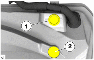
Remove the plug (1) and the cover (2).
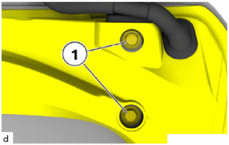
Loosen bolts (1) until the back door panel sub-assembly can be moved.
Adjust back door panel sub-assembly laterally and longitudinally to the correct gap dimension.
Tighten the bolts (1).
- Torque:
- 28.0 N*m (286 kgf*cm, 21 ft.*lbf)
Insert the plug (1) and the cover (2).
64716D
7.INSTALL DECK TRIM REAR COVER
81604
8.INSTALL TRIANGLE REFLECTOR SET
64711B
9.INSTALL DECK BOARD ASSEMBLY
64330D
10.INSTALL PACKAGE TRAY TRIM PANEL ASSEMBLY