AUDIO / VIDEO LUGGAGE SPEAKER REMOVAL
CAUTION / NOTICE / HINT
- CAUTION:
- ·
Working on 12 V vehicle electrical system.
Risk of short circuits! Risk of fire!
-Detach battery earth lead from battery.
- NOTICE:
- ·
Before performing work on electronic components, disconnect the cable from the negative (-) battery terminal to prevent damage to the electrical system or components.
·When disconnecting the cable, turn the START-STOP button (engine switch) and headlight switch off and loosen the cable nut completely. Perform these operations without twisting or prying on the cable. Then disconnect the cable.
·Clock settings, radio settings, audio system memory, DTCs and other data will be cleared when the cable is disconnected from the negative (-) battery terminal. Write down any necessary data before disconnecting the cable.
PROCEDURE

 1.REMOVE CONSOLE BOX ASSEMBLY
64330D
2.REMOVE PACKAGE TRAY TRIM PANEL ASSEMBLY
64711B
3.REMOVE DECK BOARD ASSEMBLY
w/ Spare Tire:
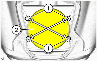
Detach the straps (1) to remove the spare wheel cover (2).

|
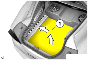
Remove in this Direction |
Slightly lift the deck board assembly (1) on the right side with a suitable tool.
Slide the left edge of the deck board assembly (1) into the recess in the direction of the arrow of the deck board assembly.
|
|
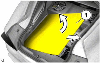
Remove in this Direction |
Remove the deck board assembly (1) in the direction of the arrow.
62480A
4.REMOVE ROOF SIDE INNER GARNISH ASSEMBLY LH
62470A
5.REMOVE ROOF SIDE INNER GARNISH ASSEMBLY RH
- HINT:
-
Use the same procedure as for the LH side.
64288D
6.SEPARATE TRANSVERSE PIPE TRIM
62609
7.REMOVE SEAT BELT HOLE COVER SUB-ASSEMBLY LH
62608
8.REMOVE SEAT BELT HOLE COVER SUB-ASSEMBLY RH
- HINT:
-
Use the same procedure as for the LH side.
64277L
9.REMOVE TRANSVERSE PIPE
62420A
10.REMOVE CENTER PILLAR GARNISH ASSEMBLY LH
62410A
11.REMOVE CENTER PILLAR GARNISH ASSEMBLY RH
- HINT:
-
Use the same procedure as for the LH side.
62636A
12.REMOVE QUARTER TRIM UPPER PANEL LH
62635A
13.REMOVE QUARTER TRIM UPPER PANEL RH
- HINT:
-
Use the same procedure as for the LH side.
81604
14.REMOVE TRIANGLE REFLECTOR SET
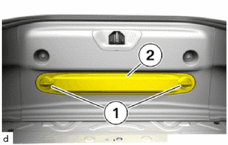
Open the screw caps (1) and the lid of the triangle reflector set (2).
- HINT:
-
Perform this procedure only when opening the lid is necessary.
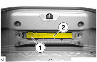
Open the hook and loop fastener (1) to remove the triangle reflector set (2).
64716D
15.REMOVE DECK TRIM REAR COVER
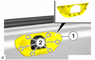
Detach the claws (2) to remove the back door striker cover (1).
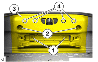
Loosen T30 screws (1).
Detach the clips (2).
Remove the deck trim rear cover (3) out under the back door weatherstrip.
Detach the deck trim rear cover (3) upward from the clips (4).
81330
16.REMOVE NO. 1 LUGGAGE COMPARTMENT LIGHT ASSEMBLY
66311
17.REMOVE ROPE HOOK (w/ Courtesy Light)
- HINT:
-
Use the same procedures for the opposite side.

|
Open in this Direction |
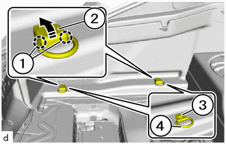
Detach the claws (1) to open the covers (2) in the direction of the arrow.
- NOTICE:
-
Because the cover will be damaged, be sure the replace to rope hook with a new one.
Loosen the T40 bolts (3) to remove the rope hooks (4).
64740B
18.REMOVE DECK TRIM SIDE BOARD AND DECK SIDE TRIM COVER LH
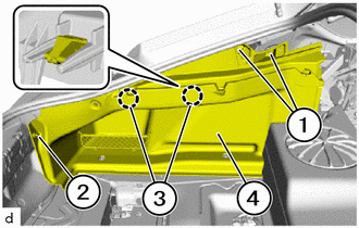
Loosen T20 screws (1).
Detach the clip (2).
Detach the clips (3).
Thread the deck trim side board and deck side trim cover LH (4) out under the back door weatherstrip.
Feed out and remove the deck trim side board and deck side trim cover LH (4).
64730C
19.REMOVE DECK TRIM SIDE BOARD AND DECK SIDE TRIM COVER RH
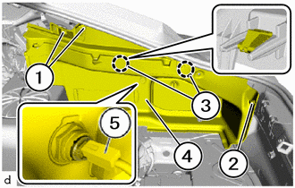
Loosen T20 screws (1).
Detach the clip (2).
Detach the deck trim side board and deck side trim cover RH (4) at the clips (3).
Thread the deck trim side board and deck side trim cover RH (4) out under the back door weatherstrip.
w/ Courtesy Light:
Unlock plug connection (5) and disconnect.
Feed out and remove the deck trim side board and deck side trim cover RH (4).
64285C
20.REMOVE LUGGAGE COMPARTMENT TRIM REAR COVER
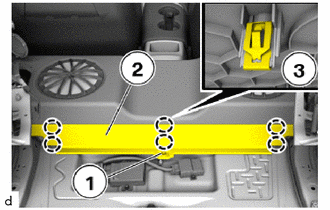
Detach the clip (1).
Detach the clips (3) to remove the luggage compartment trim rear cover (2).
67914
21.REMOVE FRONT DOOR SCUFF PLATE LH
67913
22.REMOVE FRONT DOOR SCUFF PLATE RH
- HINT:
-
Use the same procedure as for the LH side.
23.REMOVE QUARTER TRIM LOWER PANEL LH
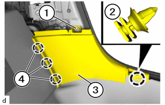
Loosen nut (1).
Using a clip remover, detach the clip (2).
Remove the quarter trim lower panel LH (3) from the guides (4) to the top.
24.REMOVE QUARTER TRIM LOWER PANEL RH
- HINT:
-
Use the same procedure as for the LH side.
86160Z
25.REMOVE REAR NO. 3 SPEAKER ASSEMBLY (for 12 Speakers)
86160Y
26.REMOVE REAR NO. 2 SPEAKER ASSEMBLY (for 10 Speakers)
- HINT:
-
Use the same procedure as for the No. 3 speaker.
72996K
27.REMOVE CHILD RESTRAINT SEAT COVER
- HINT:
-
Use the same procedures for the opposite side.
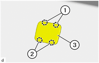
Detach the claws (1) and guides (2) to remove the child restraint seat cover (3).
64717E
28.REMOVE LUGGAGE COMPARTMENT TRIM FRONT COVER
w/ extinguisher:
Detach the strap to remove the extinguisher.
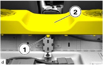
Detach the clip (1) from the luggage compartment trim front cover (2).
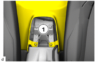
Loosen nuts (1).
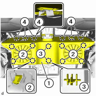
Detach the clips (2), guides (3) and guides (4) to remove the luggage compartment trim front cover (1) to the top.
86160B
29.REMOVE REAR SPEAKER ASSEMBLY
- HINT:
- ·
Use the same procedure for the RH side and LH side.
·The following procedure is for the LH side.
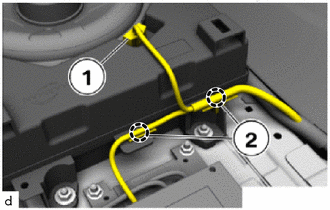
Unlock plug connection (1) and disconnect.
Detach the clamps (2).
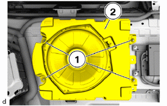
Loosen nuts (1).
Remove the rear speaker assembly (2).
64034A
30.REMOVE REAR SPEAKER GRILLE SUB-ASSEMBLY LH
- HINT:
-
Perform this procedure only when replacement of the rear speaker grille sub-assembly LH is necessary.
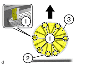

|
Front Side |
Detach the clips (1) and guide (2) to remove the rear speaker grille sub-assembly LH (3).
64033A
31.REMOVE REAR SPEAKER GRILLE SUB-ASSEMBLY RH
- HINT:
- ·
Perform this procedure only when replacement of the rear speaker grille sub-assembly RH is necessary.
·Use the same procedure as for the LH side.
64715C
32.REMOVE DECK SIDE TRIM COVER LH
- HINT:
-
Perform this procedure only when replacement of the deck side trim cover LH is necessary.
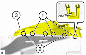

|
Protective Tape |
Using a screwdriver with its tip wrapped in protective tape, detach the claws (1).
Detach the guides (2) to remove the deck side trim cover LH (3) from the deck trim side board LH.
64714C
33.REMOVE DECK SIDE TRIM COVER RH
- HINT:
- ·
Perform this procedure only when replacement of the deck side trim cover RH is necessary.
·Use the same procedure as for the LH side.
34.REMOVE ROOM PARTITION BAND ASSEMBLY (w/ Courtesy Light)
- HINT:
-
Perform this procedure only when replacement of the room partition band assembly is necessary.
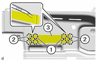
Using a molding remover A, detach the claws (1) and guides (2) to remove the room partition band assembly (3) .
64230A
35.REMOVE ROOM PARTITION NET ASSEMBLY (w/ Courtesy Light)
- HINT:
-
Perform this procedure only when replacement of the room partition net assembly is necessary.
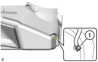
Using a clip remover, detach the clip (1).
|
|
Move in this Direction |
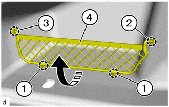
Detach the guides (1) to move the room partition net assembly (4) in the direction of the arrow.
Detach the guide (2).
Detach the guide (3) to remove the room partition net assembly (4).
64718A
36.REMOVE DECK TRIM SERVICE HOLE COVER
- HINT:
-
Perform this procedure only when replacement of the deck trim service hole cover is necessary.
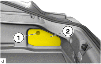
Unlock the screw cap (1) clockwise to open the flap in the deck Trim service hole cover (2).
Remove the deck Trim service hole cover (2).
61758D
37.REMOVE PIVOT MOUNTING SUPPORT LH
- HINT:
-
Perform this procedure only when replacement of the pivot mounting support LH is necessary.
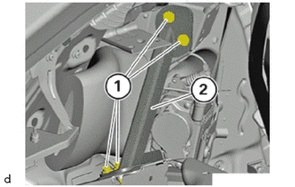
Remove the bolts (1) and pivot mounting support LH (2).
61757D
38.REMOVE PIVOT MOUNTING SUPPORT RH
- HINT:
- ·
Perform this procedure only when replacement of the pivot mounting support RH is necessary.
·Use the same procedure as for the LH side.