B48 INTAKE / EXHAUST TURBOCHARGER INSTALLATION
PROCEDURE

 15474
1.INSTALL TURBO OIL OUTLET PIPE
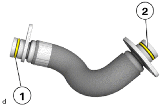
Replace No. 1 turbo oil outlet gasket (1) and (2).
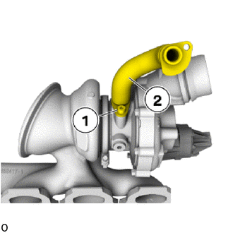
Position turbo oil outlet pipe (2) for the turbocharger sub-assembly.
Tighten down T30 bolt (1).
- Torque:
- 8.0 N*m (82 kgf*cm, 71 in.*lbf)
2.INSPECT COMPONENTS PRIOR TO INSTALLATION OF TURBOCHARGER SUB-ASSEMBLY
Check the inlet turbo oil pipe sub-assembly and outlet turbo oil pipe for contamination, obstruction and damage; clean or replace if necessary.
- HINT:
-
If the inlet turbo oil pipe sub-assemblies and/or outlet turbo oil pipe are heavily contaminated, we recommend changing the engine oil and the oil filter.
Check the No. 1 turbo water pipe sub-assembly and No. 2 turbo water pipe sub-assembly for the turbocharger sub-assembly for contamination, obstruction and damage; clean or replace if necessary.
Check all bolt connections and cable connections for correct fit.
Check air cleaner for contamination and clean or replace as needed.
Check correct functioning of crankcase ventilation.
Replace all gaskets
17201
3.INSTALL TURBOCHARGER SUB-ASSEMBLY
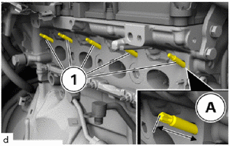
Check screw-in depth (A) of the upper stud bolt (1); if necessary, further screw in or unscrew the stud bolt.
- Screw-in Depth of Upper Stud Bolt on Cylinder Head:
32 mm (1.26 in.)
Secure stud bolt (1) with bolt locking if necessary.
- Adhesive:
Screw Lock Loctite 273, High Strength
- NOTICE:
- ·
Damage to the surface.
The use of metal-cutting tools (e.g. emery cloth) to clean the surfaces can damage them and lead to leaks or engine damage.
-Do not use any metal-cutting tools.
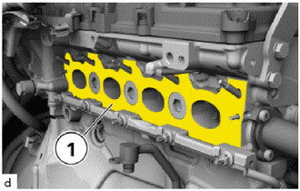
Clean sealing surfaces on the turbocharger sub-assembly and on the cylinder head sub-assembly (1).
Replace exhaust manifold to head gasket.
- NOTICE:
-
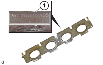
-
Mount the exhaust manifold to head gasket so that the part number (1) remains legible.
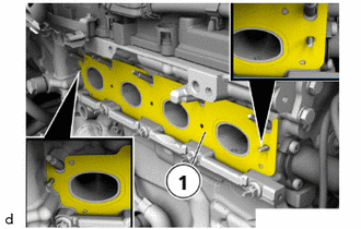
Position exhaust manifold to head gasket (1) on the cylinder head sub-assembly.
- NOTICE:
-
Make sure the exhaust manifold to head gasket (1) is installed in correct position.
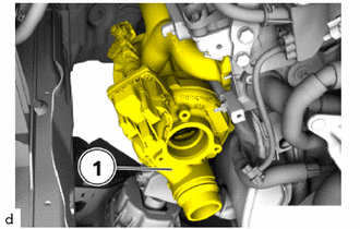
Insert the turbocharger sub-assembly (1) and position it on the clamping strip.
- NOTICE:
- ·
Protect the turbocharger sub-assembly (1) from falling.
·Note the installation position of the component. The component may be installed in various installation positions.
Position the No. 2 turbocharger stay.
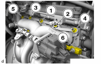
Check the turbocharger sub-assembly is installed in the correct position on the clamping strip (6).
Replace nuts (1) to (5).
Tighten nuts in sequence (1) to (5).
- Torque:
- 16 N*m (163 kgf*cm, 12 ft.*lbf)
Connect connectors and lock.
Fill turbocharger sub-assembly up to the top with engine oil using the inlet turbo oil pipe sub-assembly connection.
- Engine Oil:
Toyota Genuine Motor Oil SN 0W-20 C5 for GR Toyota Supra
- NOTICE:
-
Observe the sign in the engine compartment! Only pour in approved engine oil with the correct SAE viscosity classification.
16028
4.INSTALL NO. 2 TURBO WATER PIPE SUB-ASSEMBLY
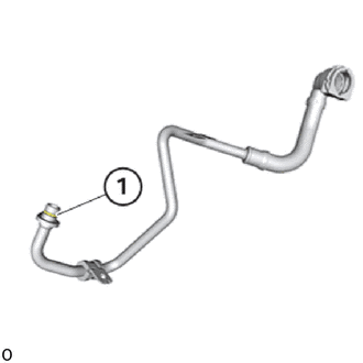
Replace the gasket (for No. 2 turbo water pipe).
Position the No. 2 turbo water pipe sub-assembly for the turbocharger sub-assembly.
Tighten down T30 bolt.
- Torque:
- 8.0 N*m (82 kgf*cm, 71 in.*lbf)
16027
5.INSTALL NO. 1 TURBO WATER PIPE SUB-ASSEMBLY
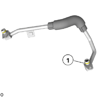
Replace the gasket (for turbo water pipe).
Position the No. 1 turbo water pipe sub-assembly for the turbocharger sub-assembly.
Tighten down T30 bolt.
- Torque:
- 8.0 N*m (82 kgf*cm, 71 in.*lbf)
15474
6.INSTALL TURBO OIL OUTLET PIPE
Position turbo oil outlet pipe for the turbocharger sub-assembly on the engine block sub-assembly.
Tighten down T30 bolt.
- Torque:
- 8.0 N*m (82 kgf*cm, 71 in.*lbf)
15407
7.INSTALL TURBO OIL INLET PIPE SUB-ASSEMBLY
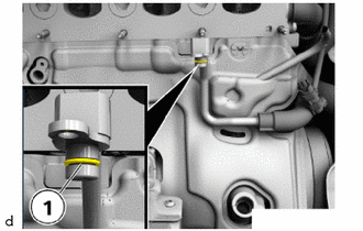
Replace the gasket (for turbo oil inlet pipe) (1).
Position turbo oil inlet pipe sub-assembly on turbocharger sub-assembly.
Tighten down T30 bolt.
- Torque:
- 8.0 N*m (82 kgf*cm, 71 in.*lbf)
17167
8.INSTALL NO. 1 EXHAUST MANIFOLD HEAT INSULATOR
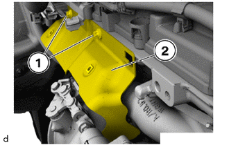
Position the No. 1 exhaust manifold heat insulator (2).
Tighten the E10 bolts (1).
- Torque:
- 19 N*m (194 kgf*cm, 14 ft.*lbf)
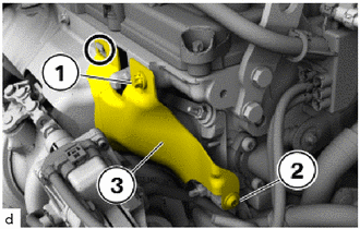
Attach No. 1 exhaust manifold heat insulator (3) in marked area.
Tighten down E10 bolt (1).
- Torque:
- 19 N*m (194 kgf*cm, 14 ft.*lbf)
Tighten down T30 bolt (2).
- Torque:
- 19 N*m (194 kgf*cm, 14 ft.*lbf)
25051
9.INSTALL EXHAUST MANIFOLD CONVERTER SUB-ASSEMBLY
82261A
10.CONNECT ALTERNATOR WIRE
11271A
11.INSTALL REAR CYLINDER BLOCK COVER
85010
12.INSTALL FRONT WIPER MOTOR AND LINK ASSEMBLY
17882
13.INSTALL NO. 2 AIR CLEANER HOSE
14.CONNECT CABLE TO NEGATIVE BATTERY TERMINAL
15.ADD ENGINE COOLANT (for High Temperature)
16.INSPECT FOR COOLANT LEAK
17. CHECK ENGINE OIL LEVEL