B48 ENGINE MECHANICAL ENGINE WIRE HARNESS(for No. 2) REMOVAL
CAUTION / NOTICE / HINT
- CAUTION:
- ·
Working on 12 V vehicle electrical system.
Risk of short circuits! Risk of fire!
-Detach battery earth lead from battery.
-For an auxiliary battery: Disconnect battery earth lead of auxiliary battery.
- NOTICE:
- ·
Damage to battery terminal, the safety battery terminal or the intelligent battery sensor (IBS).
Damaged battery terminals can lead to malfunctions or vehicle electrical system faults.
-Pull off battery terminal from battery pole by carefully moving to and fro. Do not pry off using a tool.
PROCEDURE

 1.DISCONNECT CABLE FROM NEGATIVE BATTERY TERMINAL
Click hereGeneral>MAINTENANCE>B48 BATTERY>REMOVAL
85010
2.REMOVE FRONT WIPER MOTOR AND LINK ASSEMBLY
55788A
3.REMOVE COWL TOP VENTILATOR LOUVER PROTECTOR
12601B
4.REMOVE NO. 1 ENGINE COVER SUB-ASSEMBLY
11271A
5.REMOVE REAR CYLINDER BLOCK COVER
6.REMOVE NO. 2 CYLINDER BLOCK SIDE COVER
17700
7.REMOVE AIR CLEANER ASSEMBLY
17880
8.REMOVE AIR CLEANER HOSE ASSEMBLY
82122
9.REMOVE NO. 2 ENGINE WIRE
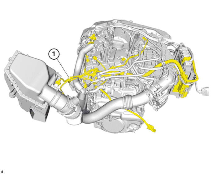
Overview: No. 2 engine wire
- NOTICE:
- ·
Damage to wires when disconnecting connectors and plug connections.
Sheared wires can cause a short circuit.
-Do not pull on the wires when disconnecting connectors and plug connections.
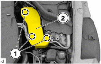
Release snap-lock couplings (1).
Feed the cover (2) out toward the top and remove.
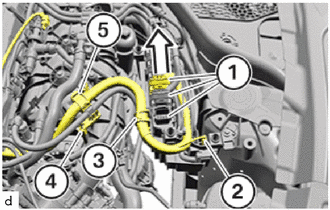
Unlock and loosen all connectors (1) in the direction of the arrow.
Unlock the holder (2).
Unlock the holder (3).
Unlock the holder (4).
Unlock the holder (5).
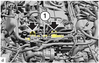
Unlock the locks (arrows).
Feed out cable channel (1) and set it aside.
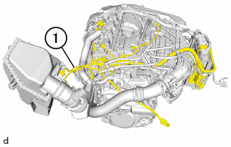
Unlock and detach the connector of the oil temperature sensor at the cylinder head.
Unlock and detach the connector of the intake mass air flow meter sub-assembly.
Unlock and detach the connector of the camshaft position sensor (for Intake Side).
Unlock and detach the connector of the camshaft position sensor (for Exhaust Side).
Unlock and detach the connector of the fuel delivery pipe.
Unlock and detach the connector of the fuel pump assembly (for High Pressure).
Unlock and detach the connector of the ventilation hose.
Unlock and detach the connector of the water pump assembly (for Heater).
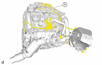
Unlock connector of wide range air fuel ratio sensor and release.
Unlock the connector of the oxygen sensor and release.
Unlock and detach the connector of the turbocharger actuator and link assembly.
Unlock and disconnect the connector from both cam timing oil control solenoid assemblies.
Unlock and detach the connector of the No. 1 check valve.
Unlock and detach all clamps.
Feed out the No. 2 engine wire (1) and remove it.