B48 ENGINE CONTROL CAMSHAFT TIMING GEAR BOLT REMOVAL
CAUTION / NOTICE / HINT
- NOTICE:
- ·
Damage to battery terminal, the safety battery terminal or the battery state sensor.
Damaged battery terminals can lead to malfunctions or vehicle electrical system faults.
-Pull off battery terminal from battery pole by carefully moving to and fro. Do not pry off using a tool.
PROCEDURE

 1. DISCHARGE FUEL SYSTEM PRESSURE
2.DISCONNECT CABLE FROM NEGATIVE BATTERY TERMINAL
Click hereGeneral>MAINTENANCE>B48 BATTERY>REMOVAL
12180E
3.REMOVE OIL FILLER CAP ASSEMBLY
12101A
4.REMOVE OIL PAN DRAIN PLUG
12101A
5.INSTALL OIL PAN DRAIN PLUG
6.REMOVE AND INSTALL HOOD SUPPORT ASSEMBLY
12601B
7.REMOVE NO. 1 ENGINE COVER SUB-ASSEMBLY
8.REMOVE NO. 2 CYLINDER BLOCK SIDE COVER
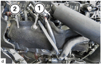
Loosen T25 screw (1).
Remove the clip.
Guide out the No. 2 cylinder block side cover (2).
17882
9.REMOVE NO. 2 AIR CLEANER HOSE
11271A
10.REMOVE REAR CYLINDER BLOCK COVER
53681
11.REMOVE UPPER FRONT SUSPENSION CENTER BRACE
55788A
12.REMOVE COWL TOP VENTILATOR LOUVER PROTECTOR
13.REMOVE SEALING FRAME
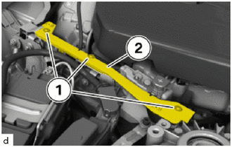
Loosen T25 screws (1).
Guide out sealing frame (2) upwards.
55789B
14.REMOVE NO. 2 COWL TOP VENTILATOR LOUVER PROTECTOR
51410
15.REMOVE NO. 1 ENGINE UNDER COVER ASSEMBLY
53896B
16.REMOVE FRONT FENDER SPLASH FRONT SHIELD LH
53895B
17.REMOVE FRONT FENDER SPLASH FRONT SHIELD RH
- HINT:
-
Use the same procedure as for the LH side.
18.DRAIN ENGINE COOLANT (for Low Temperature)
19.REMOVE INTEGRATION RELAY (for Engine Room Side)
20.REMOVE ENGINE ROOM ECM BOX
23285A
21.REMOVE NO. 1 CHECK VALVE
17111
22.REMOVE INTAKE MANIFOLD
11401T
23.REMOVE CYLINDER BLOCK COVER
15370J
24.REMOVE CAM TIMING OIL CONTROL SOLENOID ASSEMBLY
25.REMOVE SPARK PLUG
23801P
26.REMOVE NO. 1 FUEL PIPE SUB-ASSEMBLY
23802B
27.REMOVE NO. 2 FUEL PIPE SUB-ASSEMBLY
23100X
28.REMOVE FUEL (ENGINE ROOM SIDE) PUMP ASSEMBLY
23250
29.REMOVE FUEL INJECTOR ASSEMBLY
11201
30.REMOVE CYLINDER HEAD COVER SUB-ASSEMBLY
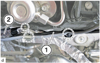
Detach both oxygen sensor cables (1) in the marked areas.
Release the positive battery cable (2) in the marked area.
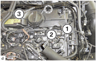
Unlock and disconnect the two spark plug connections (1).
Unlock and disconnect the ventilation hose (2).
Release the engine wiring harness (3) in the marked area.
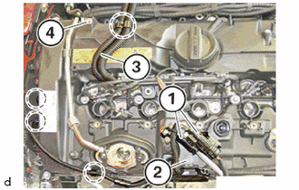
Loosen both oxygen sensor connectors (1) from the carrier plate.
Loosen the bolt (2) and put the carrier plate to one side.
Release cable in the marked areas.
Release the engine wiring harness (3) in the marked area.
Loosen screw (4) and lay the No. 2 fuel pipe sub-assembly to one side.
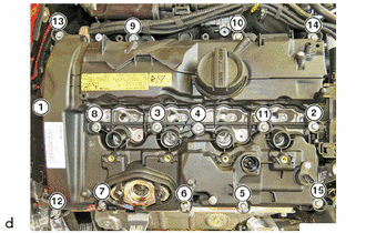
Loosen E10 bolts in the order (15) to (1).
Remove cylinder head cover sub-assembly.
31.SET NO. 1 CYLINDER TO TDC (COMPRESSION)
13540
32.REMOVE NO. 1 CHAIN TENSIONER ASSEMBLY
135A0
33.LOOSEN INTAKE CAMSHAFT TIMING GEAR BOLT ASSEMBLY
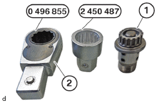
To release the intake camshaft timing gear bolt assembly (1) use a SST and reversible ratchet (2) from the special tool 0 496 855 with the special tool 2 450 487.
- SST
- 09200-WA470
09200-WA800
09900-WA280
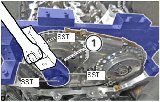
Release the intake camshaft timing gear bolt assembly (1).
135A0A
34.LOOSEN EXHAUST CAMSHAFT TIMING GEAR BOLT ASSEMBLY
To release the exhaust camshaft timing gear bolt assembly (1) use a SST and reversible ratchet (2) from the special tool 0 496 855 with the special tool 2 450 487.
- SST
- 09200-WA470
09200-WA800
09900-WA280
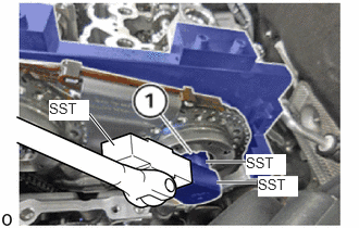
Release the exhaust camshaft timing gear bolt assembly (1).
135A0
35.REMOVE INTAKE CAMSHAFT TIMING GEAR BOLT ASSEMBLY
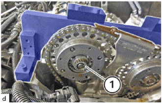
Guide out and remove the intake camshaft timing gear bolt assembly (1).
135A0A
36.REMOVE EXHAUST CAMSHAFT TIMING GEAR BOLT ASSEMBLY
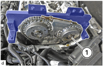
Guide out and remove the exhaust camshaft timing gear bolt assembly (1).