REAR SUSPENSION REAR SUSPENSION MEMBER BODY MOUNTING CUSHION REMOVAL
CAUTION / NOTICE / HINT
- CAUTION:
- ·
Motor vehicle may slip off the vehicle hoist where components are supported.
Danger! Life-threatening injuries!
-Secure the vehicle hoist against lowering and lifting.
- ·
Motor vehicle may slip off the vehicle hoist if the weight is distributed unevenly.
Danger! Life-threatening injuries!
-Ensure there is a specific weight compensation on the motor vehicle.
- ·
Vehicle may slip off the vehicle hoist if the vehicle hoist is handled incorrectly.
Danger! Life-threatening injuries!
-Observe safety information on raising the vehicle using a vehicle hoist.
-For additional information see:
Click hereGeneral>INTRODUCTION>REPAIR INSTRUCTION>VEHICLE LIFT AND SUPPORT LOCATIONS
PROCEDURE

 1.REMOVE REAR WHEEL
65638
2.REMOVE REAR WHEEL HOUSE LINER LH
- HINT:
-
Use the same procedure as for the RH side.
65637
3.REMOVE REAR WHEEL HOUSE LINER RH
48738
4.REMOVE REAR SUSPENSION ARM COVER LH
48737
5.REMOVE REAR SUSPENSION ARM COVER RH
- HINT:
-
Use the same procedure as for the LH side.
89516P
6.SEPARATE REAR SKID CONTROL SENSOR WIRE LH
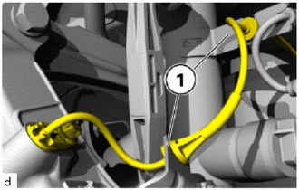
Detach the rear skid control sensor wire LH from the brackets (1).
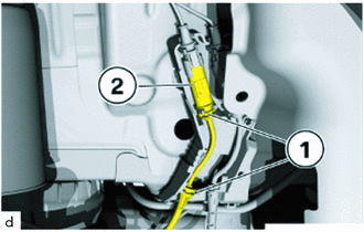
Detach the rear skid control sensor wire LH from the brackets (1).
Unlock plug connection (2) and disconnect.
89516N
7.SEPARATE REAR SKID CONTROL SENSOR WIRE RH
- HINT:
-
Use the same procedure as for the LH side.
8.SEPARATE PAD WEAR INDICATOR WIRE ASSEMBLY (for RH Side)
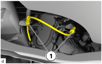
Detach the cable of the pad wear indicator wire assembly from the holders (1).
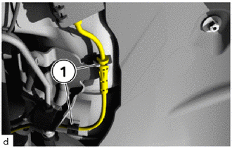
Detach the cable of the pad wear indicator wire assembly from the holders (1).
9.SEPARATE REAR FLEXIBLE HOSE LH
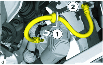
Feed out rear flexible hose LH (1) from the holder (2).
10.SEPARATE REAR FLEXIBLE HOSE RH
- HINT:
-
Use the same procedure as for the LH side.
11.SEPARATE WIRE HARNESS
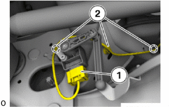
Unlock plug connection (1) and disconnect.
Detach wire harness of the rear height control sensor sub-assembly from the brackets (2) and lay to one side.
37100
12.REMOVE PROPELLER SHAFT WITH CENTER BEARING ASSEMBLY
13.REMOVE REAR COIL SPRING LH
14.REMOVE REAR COIL SPRING RH
- HINT:
-
Use the same procedure as for the LH side.
51206A
15.SEPARATE REAR SUSPENSION MEMBER SUB-ASSEMBLY
w/ LSD:
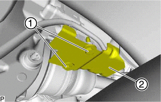
Remove the bolts (1) and rear differential protector (2).
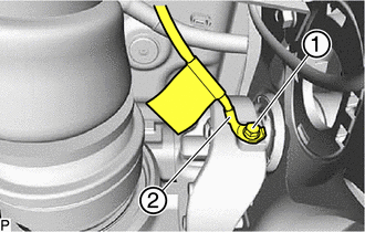
Remove the bolt (1) to disconnect the ground wire (2).
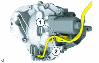
Unlock and disconnect plug connections (1).
Loosen the cable clip (2).
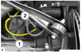
Detach the cable of the parking brake (1) from the holders (2).
- HINT:
-
Perform the operations on the left and right side.
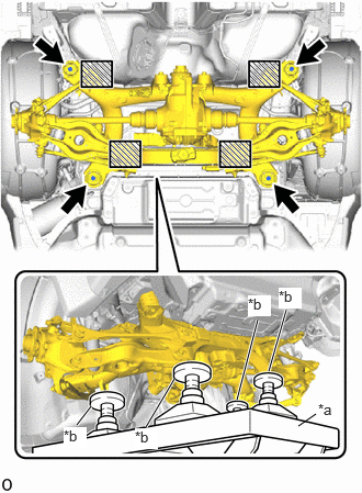
| *a | Engine Lifter |
| *b | Attachment |

|
Attachment and Wooden Block Placement Location |
Using an engine lifter and 4 attachments or equivalent tools, support the rear suspension member sub-assembly as shown in the illustration.
- CAUTION:
- ·
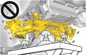
The rear suspension member sub-assembly is a very heavy component. Make sure that it is supported securely.
·If the rear suspension member sub-assembly is not securely supported, it may drop, resulting in serious injury.
- NOTICE:
-
Use attachments and wooden blocks to keep the rear suspension member sub-assembly level.
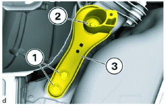
Loosen 16 mm bolts (1).
Loosen E18 bolt (2).
Remove rear lower suspension member stopper LH (3).
- HINT:
-
Perform the operations on the left and right side.
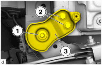
Loosen E18 bolt (1).
Loosen 16 mm bolts (2).
Remove rear suspension member rear lower brace LH (3).
- HINT:
-
Perform the operations on the left and right side.
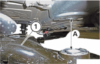
Lower the rear suspension member sub-assembly (1) by the distance (A).
- Distance (A):
Max. 100 mm (3.94 in.)
- HINT:
-
Distance (A) between rear suspension member sub-assembly and body after lowering.
52271
16.REMOVE REAR SUSPENSION MEMBER CUSHION
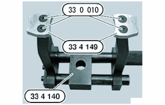
Assemble special tool 0 492 397 (33 4 140) in conjunction with 0 496 403 (33 0 012) and 0 492 406 (33 4 149).
- SST
- 09500-WA100
09500-WA270
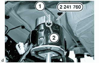
Align the notch (1) on the special tool 2 241 760 with the notch (2) on the rear suspension member sub-assembly.
- SST
- 09500-WA120
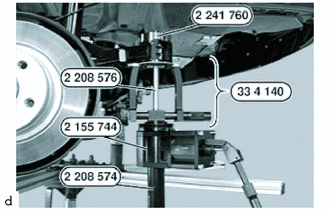
Pull the rear suspension member cushion with the special tools 2 241 760, 0 492 397 (33 4 140), 2 208 576, 2 155 744 and 2 208 574 out of the rear suspension member sub-assembly.
- SST
- 09500-WA100
09500-WA120
09500-WA220
09500-WA270
09600-WA020
52271D
17.REMOVE REAR SUSPENSION MEMBER BODY MOUNTING FRONT CUSHION
Assemble special tool 0 492 397 (33 4 140) in conjunction with 0 496 403 (33 0 012) and 0 492 406 (33 4 149).
- SST
- 09500-WA100
09500-WA270
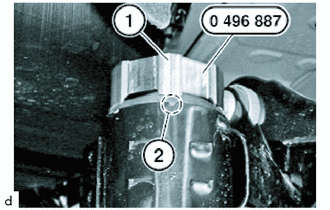
Align the notch (1) on the special tool 0 496 887 with the notch (2) on the rear suspension member sub-assembly.
- SST
- 09500-WA110
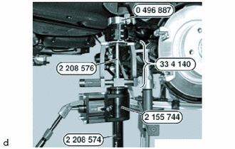
Pull the rear suspension member body mounting front cushion with the special tools 0 496 887, 0 492 397 (33 4 140), 2 208 576, 2 155 744 and 2 208 574 out of the rear suspension member sub-assembly.
- SST
- 09500-WA100
09500-WA110
09500-WA220
09500-WA270
09600-WA020