POWER DISTRIBUTION MAIN BODY ECU(for LHD) INSTALLATION
PROCEDURE

 89221
1.INSTALL MAIN BODY ECU (MULTIPLEX NETWORK BODY ECU)
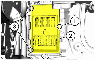
Position the main body ECU (multiplex network body ECU) (2) and thread into the guides (3).
Attach the claw (1).
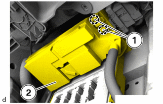
Correctly position the fuse box (2) and clip into the claws (1).
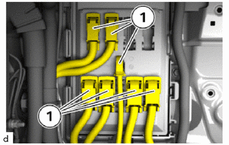
Connect all the connectors (1).
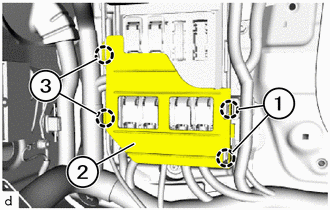
Feed the cover (2) of main body ECU (multiplex network body ECU) onto the guides (3).
Attach the claws (1).
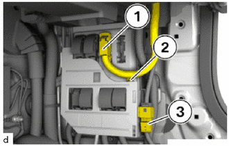
Attach the connector housing (3).
Attach the clamp (2).
Connect the connector (1).
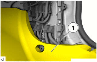
Fold back the front floor carpet assembly (1) and ensure it is positioned correctly.
62111C
2.INSTALL COWL SIDE TRIM BOARD RH
67913
3.INSTALL FRONT DOOR SCUFF PLATE RH
- HINT:
-
Use the same procedure as for the LH side.
-
Click hereVehicle Interior>INTERIOR PANELS / TRIM>INSTRUMENT PANEL SAFETY PAD>INSTALLATION
58510H
4.INSTALL FLOOR MAT ASSEMBLY
- HINT:
-
Use the same procedure as for the LH side.
-
Click hereVehicle Interior>INTERIOR PANELS / TRIM>FRONT CONSOLE BOX>INSTALLATION
87211A
5.INSTALL NO. 2 AIR DUCT
73900
6.INSTALL LOWER NO. 1 INSTRUMENT PANEL AIRBAG ASSEMBLY (w/ Knee Airbag)
55607
7.INSTALL NO. 2 INSTRUMENT PANEL UNDER COVER SUB-ASSEMBLY
55550
8.INSTALL GLOVE COMPARTMENT DOOR ASSEMBLY
55011A
9.INSTALL NO. 1 INSTRUMENT PANEL GARNISH SUB-ASSEMBLY
55317E
10.INSTALL NO. 1 INSTRUMENT SIDE PANEL
55432B
11.INSTALL INSTRUMENT PANEL FINISH LOWER PANEL
12.INSTALL CONSOLE PANEL AND CONSOLE PANEL RETAINER
58822
13.INSTALL CONSOLE SIDE PANEL
58920C
14.INSTALL FRONT CONSOLE ARMREST ASSEMBLY
15.CONNECT CABLE TO NEGATIVE BATTERY TERMINAL
for B48:
for B58:
16. ENCODE/PROGRAM CONTROL UNIT(S)
- NOTICE:
- ·
Use the most recent software version to prevent faults during programming/encoding.
·The battery voltage must not drop below 13.0 V during programming.
·Use only recommended chargers for a low-voltage vehicle electrical system.
·Do not exceed the maximum charging voltage of 14.8 V when charging the battery.
·When there is communication abnormality in the middle of work, control unit might be damaged.
·It may be necessary to perform the Action Plan several times.
Connect the battery charger to the vehicle.
Connect the diagnosis system with the vehicle.
Determine the action plan.
Service plan / Programming plan / Action plan / Calculate action plan
Accept and fully process the measures plan.
Service plan / Programming plan / Action plan / Perform action plan
Wait until programming/encoding has been completed.
- NOTICE:
-
When there is communication abnormality in the middle of work, control unit might be damaged.
Carry out vehicle test.
Vehicle management / Troubleshooting / Fault memory / Calculate test plan
Delete the fault memory.
Vehicle management / Troubleshooting / Fault memory / Delete fault memory
Disconnect the diagnosis system from the vehicle.
Disconnect the battery charger from the vehicle.
17.PERFORM INITIALIZATION
Connect the diagnosis system to the vehicle and enter the following menus:
Vehicle management / Service functions / Drive / Engine start / Reset starter lock / ABL Reset starter lock