B58 ENGINE MECHANICAL CYLINDER HEAD GASKET INSTALLATION
PROCEDURE

 11115
1.INSTALL CYLINDER HEAD GASKET
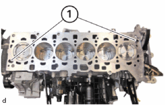
Check the ring pins (1) for damage and replace if necessary.
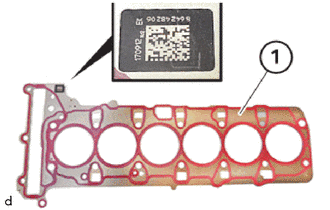
Replace cylinder head gasket (1).
Check cylinder head gasket (1) using the part number.
If the cylinder head sub-assembly is reworked, an additional thicker 0.3 mm cylinder head gasket is available for service personnel.
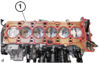
Guide in the cylinder head gasket (1) and install.
11101
2.INSTALL CYLINDER HEAD SUB-ASSEMBLY
- CAUTION:
- ·
Heavy component.
Heavy components can lead to injury or damage.
-Remove and install heavy components with the aid of another person/other persons.
- NOTICE:
- ·
Damage to threads.
Fluid in the threaded hole may damage the thread when bolts are tightened in the threads.
-Dry threaded holes (e.g. using compressed air).
- HINT:
- ·
Do not remove bolt coating.
·When replacing the cylinder head sub-assembly: The complete valve control and the Valvetronic servomotor are already pre-assembled for new cylinder head sub-assembly.
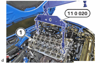
Feed in, position and install cylinder head sub-assembly (1) and turbocharger sub-assembly with the help of an auxiliary person and the special tool 0 490 567 (11 0 020).
- SST
- 09200-WA860
- NOTICE:
- ·
Damage to the guide rails.
Large amounts of force may damage the guide rails of the timing chain.
-Make sure not to damage the guide rail with the cylinder head sub-assembly when removing and installing the cylinder head sub-assembly.
Replace cylinder head T60 bolts (1) to (14).
Do not wash off coating of cylinder head T60 bolts.
Lightly oil contact surfaces of cylinder head T60 bolts screw heads.
No coolant, water or engine oil must be present in threaded holes of engine block.
- HINT:
-
When assembling, it is essential to observe bolting sequences and tightening torques.
-
Non-observance of these requirements may result in leaks and damage.
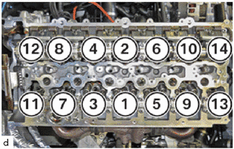
Feed in cylinder head T60 bolts (1) to (14) and install.
Bolt in cylinder head T60 bolts in sequence (1) to (14).
Tighten the cylinder head T60 bolts using the special tool 0 490 504 (00 9 120) in the sequence (1) to (14).
- SST
- 09900-WA010
- Torque:
- 30 N*m (306 kgf*cm, 22 ft.*lbf)
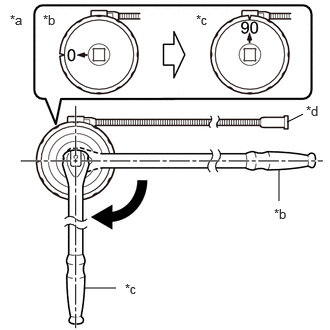
| *a | Example |
| *b | Before Tightening |
| *c | After Tightening |
| *d | Magnetic Portion |
Using SST, tighten the T60 bolts (1) to (14) an additional 90°.
- SST
- 09900-WA010
- HINT:
- ·
The magnetic portion is used to securethe gauge to the vehicle.
·After first adjusting the needle of thegauge to 0°, tighten to the specified angle.
·Perform the work procedure carefully so that the gauge, etc. does not become tilted.
| *a | Example |
| *b | Before Tightening |
| *c | After Tightening |
| *d | Magnetic Portion |
Using SST, tighten the T60 bolts (1) to (14) an additional 180°.
- SST
- 09900-WA010
- HINT:
- ·
The magnetic portion is used to securethe gauge to the vehicle.
·After first adjusting the needle of thegauge to 0°, tighten to the specified angle.
·Perform the work procedure carefully so that the gauge, etc. does not become tilted.
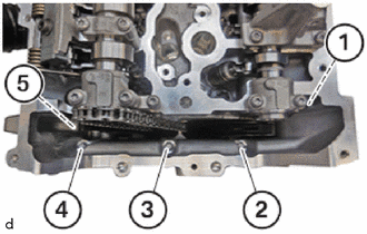
Replace cylinder head E10 bolts (1) to (5).
Make sure that there is no coolant, water or engine oil in the threaded holes of the timing case cover.
Tighten the E10 bolts (1) to (5).
- Torque:
- 19 N*m (194 kgf*cm, 14 ft.*lbf)
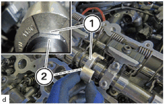
Feed in and position camshaft sensor wheel (1) on the intake camshaft sub-assembly (2).
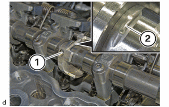
Rotate intake camshaft sub-assembly, if necessary in the position shown.
The recess (2) must point upwards.
Using 3 mm hexagon wrench, Tighten down bolt (1).
- Torque:
- 4.5 N*m (46 kgf*cm, 40 in.*lbf)
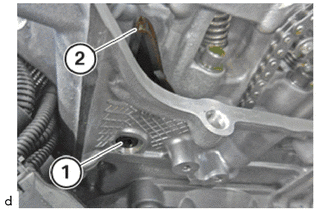
Feed in and install T45 bearing journal (1) on the No. 1 chain vibration damper (2).
Tighten the bearing journals (1).
- Torque:
- 20 N*m (204 kgf*cm, 15 ft.*lbf)
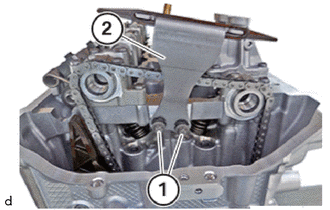
Insert chain damper guide (2) and install.
Tighten the E10 bolts (1).
- Torque:
- 8.0 N*m (82 kgf*cm, 71 in.*lbf)
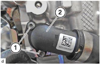
Replace the sealing ring at the No. 2 water by-pass hose (2).
Feed in and install No. 2 water by-pass hose (2).
Tighten the T30 bolts (1).
- Torque:
- 8.0 N*m (82 kgf*cm, 71 in.*lbf)
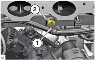
Connect connector (1) to the coolant temperature sensor (2) and lock.
Make sure that the connector (1) engages audibly on the coolant temperature sensor (2).
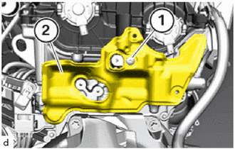
Guide in and install No. 4 engine cover (2).
Tighten the T30 bolt (1).
- Torque:
- 8.0 N*m (82 kgf*cm, 71 in.*lbf)
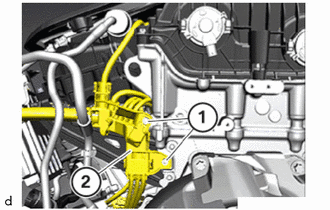
Insert and position the wiring harness section for the engine wire (2).
Tighten the T30 bolts (1).
- Torque:
- 8.0 N*m (82 kgf*cm, 71 in.*lbf)
- NOTICE:
- ·
Improper routing of cables and wiring harnesses.
Trapped, crushed or damaged cables may cause short circuits and malfunctions.
-Route all cables without abrasions, do not trap and crush.
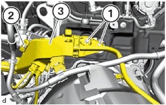
Feed in and position transmission wire (3).
Ensure that the lock (2) engages audibly.
Tighten the E8 bolts (1).
- Torque:
- 8.0 N*m (82 kgf*cm, 71 in.*lbf)
- NOTICE:
- ·
Improper routing of cables and wiring harnesses.
Trapped, crushed or damaged cables may cause short circuits and malfunctions.
-Route all cables without abrasions, do not trap and crush.
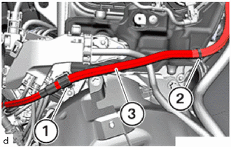
Insert and install the alternator positive battery cable (3).
Secure clamps (1) and (2).
- CAUTION:
- ·
Improper routing of cables and wiring harnesses.
Risk of short circuits!
-Route the alternator wire without abrasions and do not trap.
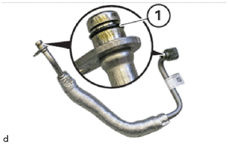
Replace the O-rings (1) using special tool 0 496 714 (00 9 030).
- SST
- 09800-WA010
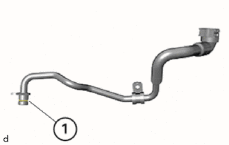
Replace the O-ring (1) using special tool 0 496 714 (00 9 030).
- SST
- 09800-WA010
for 2 Port Type:
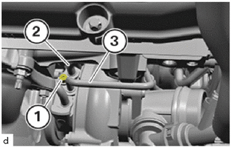
Feed in and install the inlet turbo oil pipe sub-assembly (3) for the turbocharger sub-assembly.
Insert and install the No. 2 turbo water pipe sub-assembly (2) for the turbocharger sub-assembly.
Tighten down T30 bolt (1).
- Torque:
- 8.0 N*m (82 kgf*cm, 71 in.*lbf)
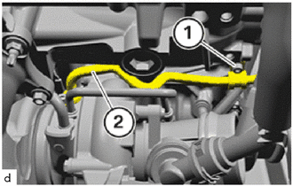
Tighten the T30 bolt (1) on the holder of the No. 2 turbo water pipe sub-assembly (2).
- Torque:
- 8.0 N*m (82 kgf*cm, 71 in.*lbf)
for 6 Port Type:
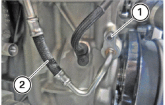
Position inlet turbo oil pipe sub-assembly (2).
Tighten down the screw (1).
- Torque:
- 8.0 N*m (82 kgf*cm, 71 in.*lbf)
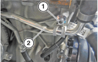
Tighten the screw (1) on the holder of the No. 2 turbo water pipe sub-assembly (2).
- Torque:
- 8.0 N*m (82 kgf*cm, 71 in.*lbf)
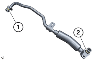
Replace O-rings (1) and (2) with the special tool 0 496 714 (00 9 030).
- SST
- 09800-WA010
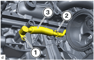
Install the No. 1 turbo water pipe sub-assembly for the turbocharger sub-assembly (3) in the cylinder block sub-assembly and tighten the T30 bolt (1).
- Torque:
- 8.0 N*m (82 kgf*cm, 71 in.*lbf)
Tighten down T30 bolt (2).
- Torque:
- 8.0 N*m (82 kgf*cm, 71 in.*lbf)
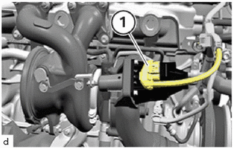
Connect connectors (1) and lock.
Make sure the connector (1) engages audibly.
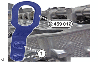
Unscrew the bolts (1) of the special tool 2 459 012 .
- SST
- 09200-WA610
Feed out the special tool 2 459 012 at the cylinder head sub-assembly and remove.
- SST
- 09200-WA610
17167
3.INSTALL NO.1 EXHAUST MANIFOLD HEAT INSULATOR (for 6 Port Type)
17293
4.INSTALL TURBOCHARGER STAY
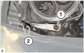
Replace the T40 bolts.
Position support and tighten with the T40 bolts (2).
- Torque:
- 19 N*m (194 kgf*cm, 14 ft.*lbf)
Replace the T40 bolt.
Tighten down bolt (1).
- Torque:
- 19 N*m (194 kgf*cm, 14 ft.*lbf)
15474
5.INSTALL OUTLET TURBO OIL PIPE
25051
6.INSTALL EXHAUST MANIFOLD CONVERTER SUB-ASSEMBLY
7.INSTALL STEERING LINK ASSEMBLY
45220
8.INSTALL STEERING INTERMEDIATE SHAFT ASSEMBLY
45047
9.CONNECT TIE ROD END SUB-ASSEMBLY LH
45046
10.CONNECT TIE ROD END SUB-ASSEMBLY RH
- HINT:
-
Perform the same procedure as for the LH side.
11.INSTALL WHEEL ASSEMBLY
13050
12.INSTALL CAMSHAFT TIMING GEAR ASSEMBLY
13070A
13.INSTALL CAMSHAFT TIMING EXHAUST GEAR ASSEMBLY