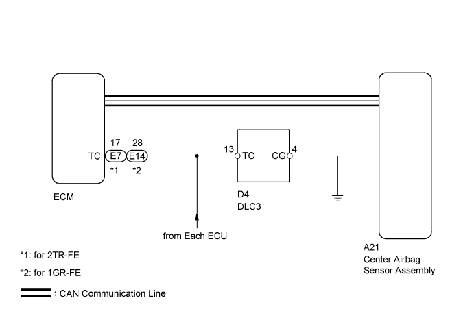
AIRBAG SYSTEM > TC and CG Terminal Circuit |
| 1.CHECK HARNESS AND CONNECTOR (DLC3 - ECM) |
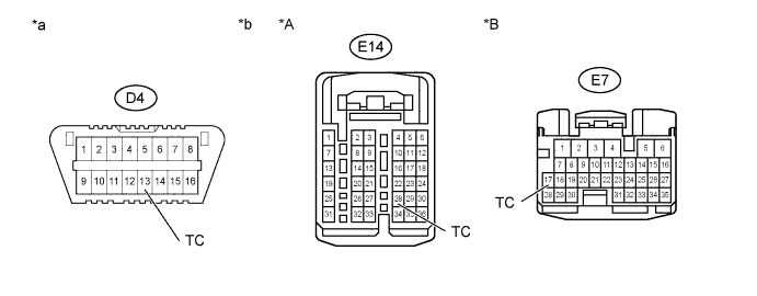
| *A | for 1GR-FE | *B | for 2TR-FE |
| *a | DLC3 | *b | Front view of wire harness connector (to ECM) |
Turn the ignition switch off.
Disconnect the connector from the ECM.
Measure the resistance according to the value(s) in the table below.
| Tester Connection | Condition | Specified Condition |
| D4-13 (TC) - E14-28 (TC) | Always | Below 1 Ω |
| Tester Connection | Condition | Specified Condition |
| D4-13 (TC) - E7-17 (TC) | Always | Below 1 Ω |
|
| ||||
| OK | |
 |
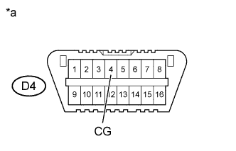
| 2.CHECK HARNESS AND CONNECTOR (CG OF DLC3 - BODY GROUND) |
 |
Measure the resistance according to the value(s) in the table below.
| Tester Connection | Condition | Specified Condition |
| D4-4 (CG) - Body ground | Always | Below 1 Ω |
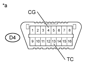
| *a | DLC3 |
|
| ||||
| OK | |
|
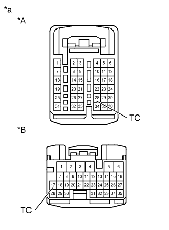
| 3.CHECK HARNESS AND CONNECTOR (TC CIRCUIT OF ECM) |
 |
Measure the resistance according to the value(s) in the table below.
| Tester Connection | Condition | Specified Condition |
| E14-28 (TC) - Body ground | Always | 1 MΩ or higher |
| Tester Connection | Condition | Specified Condition |
| E7-17 (TC) - Body ground | Always | 1 MΩ or higher |
| *A | for 1GR-FE |
| *B | for 2TR-FE |
| *a | Front view of wire harness connector (to ECM) |
|
| ||||
| OK | |
|
| 4.CHECK DTC |
 |
Using SST, connect terminals TC and CG of the DLC3.
| *a | DLC3 |
| Result | Proceed to |
| DTC output mode is set in each ECU. | A |
| DTC output mode is not set in ECM. (for 1GR-FE) | B |
| DTC output mode is not set in ECM. (for 2TR-FE) | C |
| DTC output mode is not set in center airbag sensor assembly. | D |
|
| ||||
|
| ||||
|
| ||||
| A | ||
 | ||
| ||
