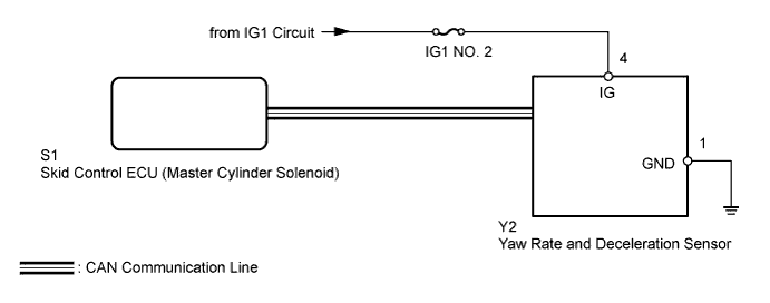
DTC C1210 Zero Point Calibration of Yaw Rate Sensor Undone |
DTC C1336 Zero Point Calibration of Acceleration Sensor Undone |
| DTC Code | DTC Detection Condition | Trouble Area |
| C1210 | Zero point calibration of the yaw rate sensor is incomplete. |
|
| C1336 | Zero point calibration of the deceleration sensor is incomplete. |
| 1.CHECK DTC (CAN COMMUNICATION SYSTEM) |
Check for DTCs (Click here).
| Result | Proceed to |
| CAN DTC is not output | A |
| CAN DTC is output | B |
|
| ||||
| A | |
 |
| 2.PERFORM ZERO POINT CALIBRATION OF YAW RATE AND DECELERATION SENSOR |
Perform zero point calibration of the yaw rate and deceleration sensor (Click here).
| NEXT | |
|
| 3.PERFORM TEST MODE (SIGNAL CHECK) |
Turn the ignition switch off.
Perform the signal check in the Test Mode Procedure (Click here).
|
| ||||
| OK | ||
 | ||
| ||
| 4.CHECK YAW RATE AND DECELERATION SENSOR INSTALLATION |
Turn the ignition switch off.
Check that the yaw rate and deceleration sensor has been installed properly (Click here).
|
| ||||
| OK | |
|
| 5.READ VALUE USING TECHSTREAM (YAW RATE AND DECELERATION SENSOR) |
Turn the ignition switch off.
Connect the Techstream to the DLC3.
Turn the ignition switch to ON.
Turn the Techstream on.
Enter the following menus: Chassis / ABS/VSC/TRAC / Data List.
| Tester Display | Measurement Item/Range | Normal Condition | Diagnostic Note |
| Deceleration Sensor | Deceleration sensor/ Min.: -18.525 m/s2, Max.: 18.387 m/s2
| - | Changes continuously during acceleration/deceleration. |
| Deceleration Sensor2 | Deceleration sensor 2/ Min.: -18.525 m/s2, Max.: 18.387 m/s2
| - | Changes continuously during acceleration/deceleration. |
| Yaw Rate Sensor | Yaw rate sensor/ Min.: -128°/s, Max.: 127°/s | 0°/s: Vehicle stationary -128 to 0°/s: Right turn 0 to 127°/s: Left turn | - |
Check that the yaw rate and deceleration sensor output value is displayed on the Techstream.
|
| ||||
| OK | ||
| ||
| ||

