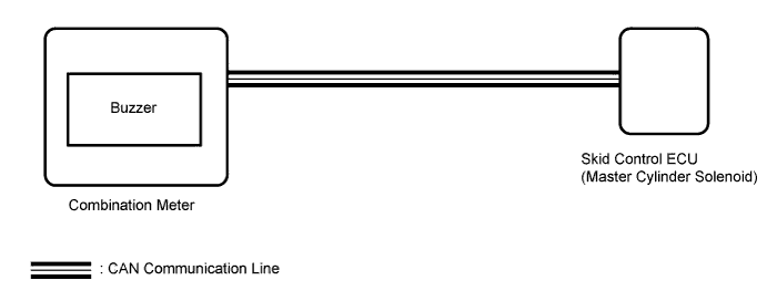
VEHICLE STABILITY CONTROL SYSTEM (for Hydraulic Brake Booster) > VSC Buzzer Circuit |
| 1.CHECK CAN COMMUNICATION LINE |
Turn the ignition switch off.
Connect the Techstream to the DLC3.
Turn the ignition switch to ON.
Turn the Techstream on.
Select CAN Bus Check from the System Selection Menu screen and follow the prompts on the screen to inspect the CAN bus (Click here).
|
| ||||
| OK | |
 |
| 2.PERFORM ACTIVE TEST USING TECHSTREAM (BUZZER) |
Connect the Techstream to the DLC3.
Turn the ignition switch to ON.
Turn the Techstream on.
Enter the following menus: Chassis / ABS/VSC/TRAC / Active Test.
According to the display on the tester, perform the Active Test.
| Tester Display | Test Part | Control Range | Diagnostic Note |
| Buzzer | VSC warning buzzer | Buzzer OFF/ON | The buzzer can be heard |
Check that the buzzer sounds or stops in accordance with the Techstream.
| Result | Proceed to |
| Buzzer does not sound or stop | A |
| Buzzer sounds and stops | B |
|
| ||||
| A | |
|
| 3.REPLACE COMBINATION METER ASSEMBLY |
Turn the ignition switch off.
Replace the combination meter (Click here).
| NEXT | |
|
| 4.PERFORM ACTIVE TEST USING TECHSTREAM (BUZZER) |
Connect the Techstream to the DLC3.
Turn the ignition switch to ON.
Turn the Techstream on.
Enter the following menus: Chassis / ABS/VSC/TRAC / Active Test.
According to the display on the tester, perform the Active Test.
| Tester Display | Test Part | Control Range | Diagnostic Note |
| Buzzer | VSC warning buzzer | Buzzer OFF/ON | The buzzer can be heard |
Check that the buzzer sounds or stops in accordance with the Techstream.
| Result | Proceed to |
| Buzzer does not sound or stop | A |
| Buzzer sounds and stops | B |
|
| ||||
| A | ||
 | ||
| ||
