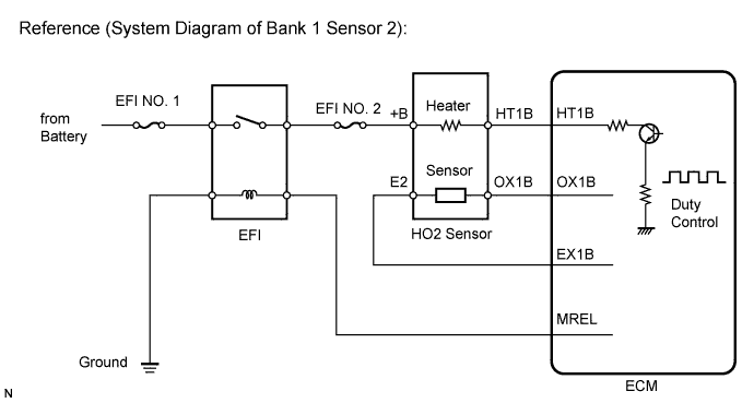
DTC P0037 Oxygen Sensor Heater Control Circuit Low (Bank 1 Sensor 2) |
DTC P0038 Oxygen Sensor Heater Control Circuit High (Bank 1 Sensor 2) |
DTC P0057 Oxygen Sensor Heater Control Circuit Low (Bank 2 Sensor 2) |
DTC P0058 Oxygen Sensor Heater Control Circuit High (Bank 2 Sensor 2) |
DTC P0141 Oxygen Sensor Heater Circuit Malfunction (Bank 1 Sensor 2) |
DTC P0161 Oxygen Sensor Heater Circuit Malfunction (Bank 2 Sensor 2) |
| DTC Code | DTC Detection Condition | Trouble Area |
| P0037 P0057 | Heated Oxygen (HO2) sensor (bank 1, 2 sensor 2) heater current less than 0.3 A (1 trip detection logic) |
|
| P0038 P0058 | Heated Oxygen (HO2) sensor (bank 1, 2 sensor 2) heater current more than 2 A (1 trip detection logic) |
|
| P0141 P0161 | Cumulative heater resistance correction value exceeds the acceptable threshold (2 trip detection logic) |
|
| Related DTCs | P0037: Heated oxygen sensor heater (bank 1 sensor 2) open/short (Low electrical current) P0038: Heated oxygen sensor heater (bank 1 sensor 2) open/short (High electrical current) P0057: Heated oxygen sensor heater (bank 2 sensor 2) open/short (Low electrical current) P0058: Heated oxygen sensor heater (bank 2 sensor 2) open/short (High electrical current) P0141: Heated oxygen sensor heater performance (bank 1 sensor 2) P0161: Heated oxygen sensor heater performance (bank 2 sensor 2) |
| Required sensors/Components (Main) | Heated oxygen sensor heater (bank 1 sensor 2) Heated oxygen sensor heater (bank 2 sensor 2) |
| Required sensors/Components (Related) | - |
| Frequency of operation | Continuous: P0037, P0038, P0057 and P0058 Once per driving cycle: P0141 and P0161 |
| Duration | 0.5 seconds: P0037 and P0057 Within 1 second: P0038 and P0058 10 seconds: P0141 and P0161 |
| MIL operation | Immediate: P0037, P0038, P0057 and P0058 2 driving cycles: P0141 and P0161 |
| Sequence of operation | None |
| Monitor runs whenever following DTCs are not present | None |
| Battery voltage | 10.5 to 20 V |
| Battery voltage | 10.5 V or more |
| Engine | Running |
| Starter | OFF |
| Battery voltage | 10.5 to 20 V |
| One of the following conditions is met: | Condition A or B |
| A. All of the following conditions are met: | Condition 1, 2, 3, 4 and 5 |
| 1. Battery voltage | 10.5 V or more |
| 2. Fuel cut | OFF |
| 3. Time after fuel cut ON to OFF | 30 seconds or more |
| 4. Accumulated heater ON time | 100 seconds or more |
| 5. Learned heater OFF current operation | Completed |
| B. Duration that rear heated oxygen sensor impedance is less than 15 kΩ | 2 seconds or more |
| Heater current | Less than 0.3 A |
| One of the following conditions is met: | Condition A or B |
| A. Learned heater OFF current | More than 2 A |
| B. Hybrid IC high current limiter port | Fail |
| Accumulated heater resistance | Varies with sensor element temperature (Example: More than 23 Ω) |
| Heated Oxygen (HO2) sensor heater current | 0.4 to 1 A (when engine idles, HO2 sensor warmed up and battery voltage 11 to 14 V) |
| 1.INSPECT HEATED OXYGEN SENSOR (HEATER RESISTANCE) |
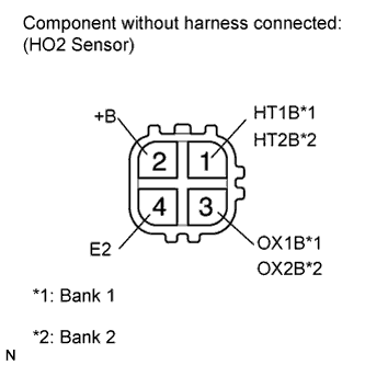 |
Disconnect the D31*1 or D32*2 heated oxygen (HO2) sensor connector.
Measure the resistance according to the value(s) in the table below.
| Tester Connection | Condition | Specified Condition |
| 1 (HT1B) - 2 (+B) | 20°C (68°F) | 11 to 16 Ω |
| 1 (HT1B) - 4 (E2) | Always | 10 kΩ or higher |
| Tester Connection | Condition | Specified Condition |
| 1 (HT2B) - 2 (+B) | 20°C (68°F) | 11 to 16 Ω |
| 1 (HT2B) - 4 (E2) | Always | 10 kΩ or higher |
|
| ||||
| OK | |
 |
| 2.CHECK TERMINAL VOLTAGE (+B OF HO2 SENSOR) |
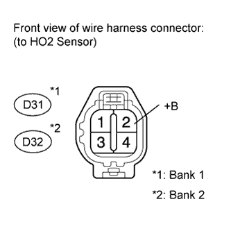 |
Disconnect the D31*1 or D32*2 HO2 sensor connector.
Measure the voltage according to the value(s) in the table below.
| Tester Connection | Switch Condition | Specified Condition |
| D31-2 (+B) - Body ground | Ignition switch ON | 11 to 14 V |
| Tester Connection | Switch Condition | Specified Condition |
| D32-2 (+B) - Body ground | Ignition switch ON | 11 to 14 V |
|
| ||||
| OK | |
|
| 3.CHECK HARNESS AND CONNECTOR (HEATED OXYGEN SENSOR - ECM) |
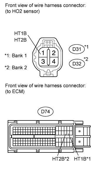 |
Disconnect the D31*1 or D32*2 HO2 sensor connector.
Disconnect the D74 ECM connector.
Measure the resistance according to the value(s) in the table below.
| Tester Connection | Condition | Specified Condition |
| D31-1 (HT1B) - D74-45 (HT1B) | Always | Below 1 Ω |
| D32-1 (HT2B) - D74-44 (HT2B) | Always | Below 1 Ω |
| Tester Connection | Condition | Specified Condition |
| D31-1 (HT1B) or D74-45 (HT1B) - Body ground | Always | 10 kΩ or higher |
| D32-1 (HT2B) or D74-44 (HT2B) - Body ground | Always | 10 kΩ or higher |
|
| ||||
| OK | ||
 | ||
| ||
| 4.INSPECT FUSE (EFI NO. 2) |
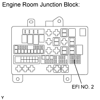 |
Remove the EFI NO. 2 fuse from the engine room junction block.
Measure the resistance according to the value(s) in the table below.
| Tester Connection | Condition | Specified Condition |
| EFI NO. 2 fuse | Always | Below 1 Ω |
|
| ||||
| OK | |
|
| 5.CHECK HARNESS AND CONNECTOR (HEATED OXYGEN SENSOR - EFI NO. 2 FUSE) |
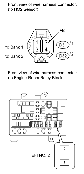 |
Disconnect the D31*1 or D32*2 HO2 sensor connector.
Remove the EFI NO. 2 fuse from the engine room relay block.
Measure the resistance according to the value(s) in the table below.
| Tester Connection | Condition | Specified Condition |
| D31-2 (+B) - EFI NO. 2 fuse (2) | Always | Below 1 Ω |
| D32-2 (+B) - EFI NO. 2 fuse (2) | Always | Below 1 Ω |
| Tester Connection | Condition | Specified Condition |
| D31-2 (+B) or EFI NO. 2 fuse (2) - Body ground | Always | 10 kΩ or higher |
| D32-2 (+B) or EFI NO. 2 fuse (2) - Body ground | Always | 10 kΩ or higher |
|
| ||||
| OK | |
|
| 6.CHECK HARNESS AND CONNECTOR (INTEGRATION RELAY - EFI NO. 2 FUSE) |
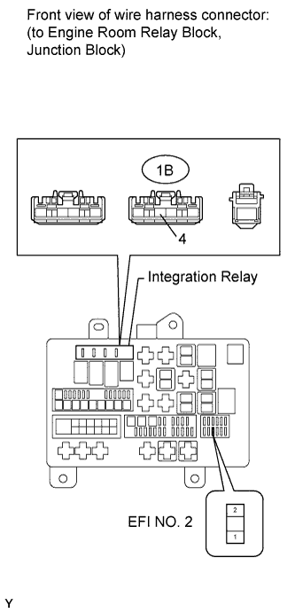 |
Remove the EFI NO. 2 fuse from the engine room relay block.
Remove the integration relay from the engine room junction block .
Measure the resistance according to the value(s) in the table below.
| Tester Connection | Condition | Specified Condition |
| EFI NO. 2 fuse (1) - 1B-4 | Always | Below 1 Ω |
| Tester Connection | Condition | Specified Condition |
| EFI NO. 2 fuse (1) or 1B-4 - Body ground | Always | 10 kΩ or higher |
|
| ||||
| OK | ||
| ||
| ||

