 |
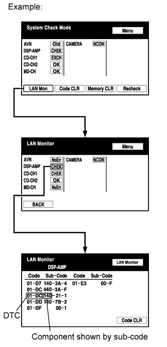
Enter the diagnostic mode.
NAVIGATION SYSTEM (for CrewMax) > Stereo Component Amplifier Communication Error |
| 1.IDENTIFY COMPONENT SHOWN BY SUB-CODE |
|
Enter the diagnostic mode.
Press the "LAN Mon" switch to change to "LAN Monitor" mode.
Identify the component shown by the sub-code.
| NEXT | |
 |
| 2.CHECK POWER SOURCE CIRCUIT OF COMPONENT SHOWN BY SUB-CODE |
Inspect the power source circuit of the component shown by the sub-code.
| Component | Proceed to |
| Navigation receiver (140) | Navigation receiver power source circuit (Click here) |
| Television display (1B0)* | Television display power source circuit (Click here)* |
| NEXT | |
|
| 3.INSPECT NAVIGATION RECEIVER |
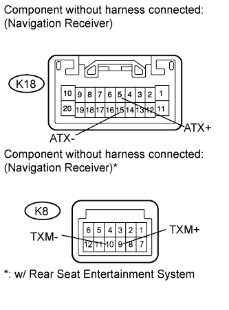 |
Disconnect the K18 and K8 receiver connectors.
Measure the resistance according to the value(s) in the table below.
| Tester Connection | Condition | Specified Condition |
| K18-5 (ATX+) - K18-15 (ATX-) | Always | 60 to 80 Ω |
| K8-9 (TXM+) - K8-10 (TXM-)* |
| Result | Proceed to |
| OK | A |
| NG (for Column Shift Type) | B |
| NG (for Floor Shift Type) | C |
|
| ||||
|
| ||||
| A | |
|
| 4.CHECK HARNESS AND CONNECTOR (STEREO COMPONENT AMPLIFIER - COMPONENT SHOWN BY SUB-CODE) |
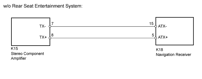
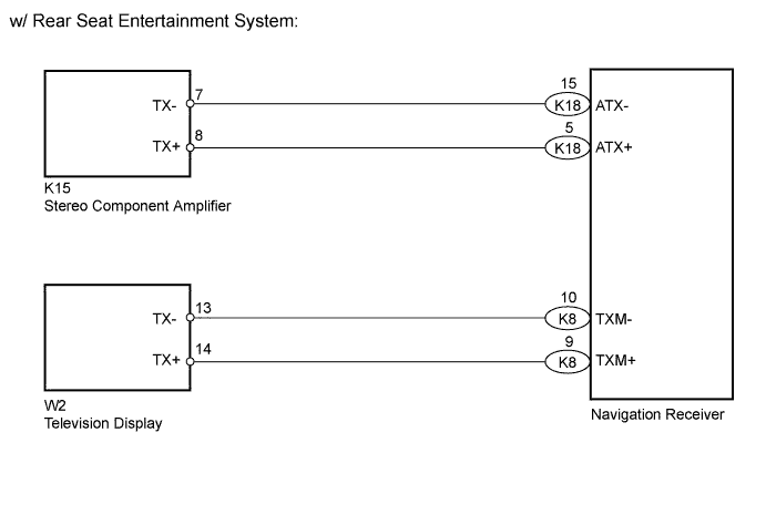
Referring to the AVC-LAN wiring diagram below, check the AVC-LAN circuit between the stereo component amplifier and the component shown by the sub-code.
Disconnect all connectors between the stereo component amplifier and the component shown by sub-code.
Check for an open or short in the AVC-LAN circuit between the stereo component amplifier and the component shown by the sub-code.
|
| ||||
| OK | |
|
| 5.REPLACE COMPONENT SHOWN BY SUB-CODE |
Replace the component shown by the sub-code with a normal one and check if the same problem occurs again.
|
| ||||
| OK | ||
 | ||
| ||
