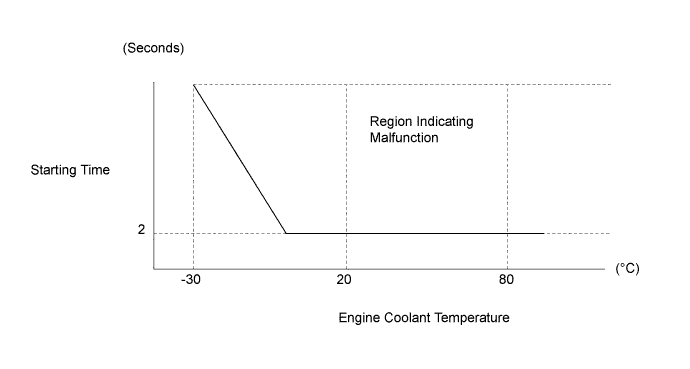
DTC P1604 Startability Malfunction |
| DTC No. | DTC Detection Condition | Trouble Area |
| P1604 | Either condition is met:
|
|
| Reference waveforms showing a normal cold engine start |
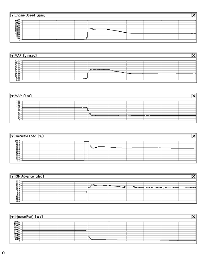
| Reference waveforms showing a normal warm engine start |
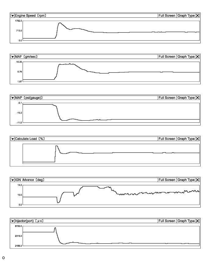
| Reference waveforms showing an engine stop after normal idling |
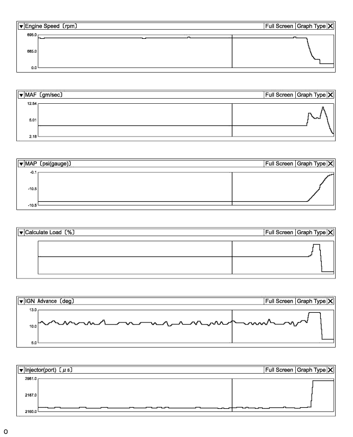
| Reference values when there is an air leak in the intake system during starting difficulty |
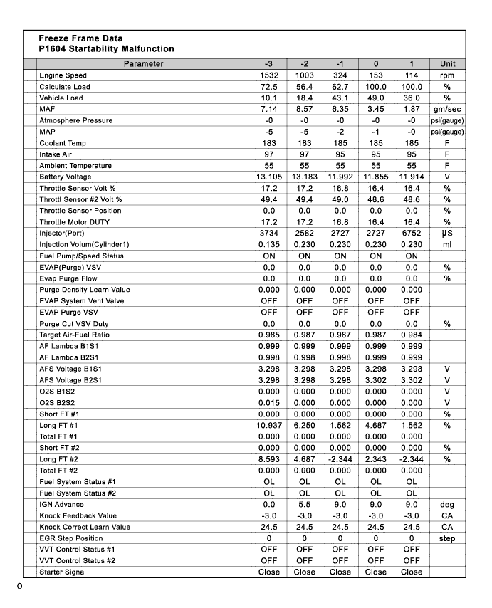
| Malfunction Recurrence and Inspection Areas |
Freeze frame data exists, but the malfunction (starting difficulty) has not reoccurred and the malfunction conditions are unknown.
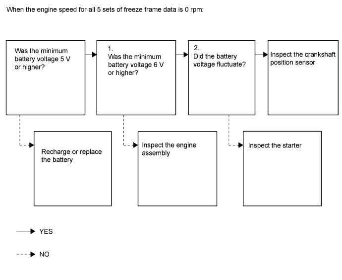
The engine speed recorded in the freeze frame data is 0 rpm (the engine does not crank).
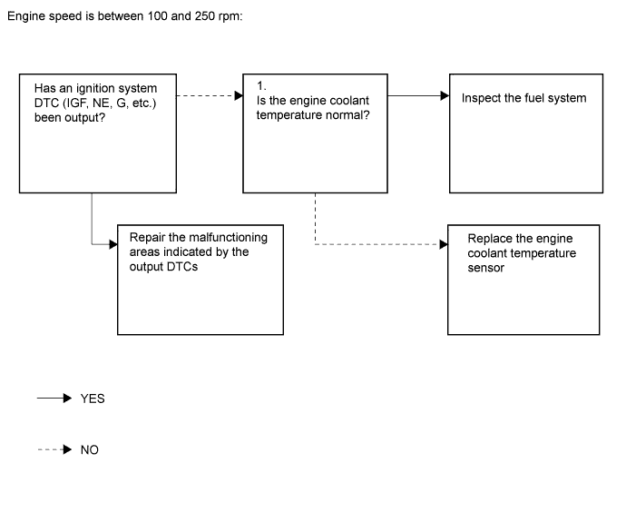
All engine speeds recorded in the freeze frame data are between 100 and 250 rpm (the engine cranks but there is no combustion).
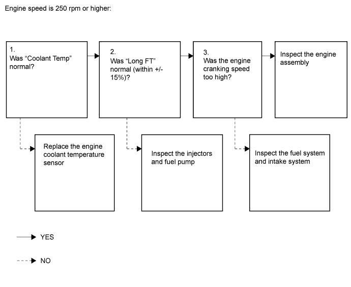
The engine speed recorded in the freeze frame data is 250 rpm or higher (the initial combustion and starter turnoff timing is too late).
When the malfunction (starting difficulty) can be reproduced, or malfunction conditions are known, perform the following inspections ("Problem symptoms" and "Systems to inspect")
Problem symptoms
Systems to inspect.
| INSPECTION FLOW |
Freeze frame data exists, but the malfunction (starting difficulty) has not reoccurred and the malfunction conditions are unknown.
| Freeze Frame Data Item | Result | Suspected Area | Procedure |
| Engine Speed | 0 rpm (no engine cranking at all) |
| 4 to 9 |
| 100 to 250 rpm (engine cranks but no initial combustion*1) |
| 10 to 14 | |
| 250 rpm or higher (combustion occurs but initial combustion and starter turnoff*2 occur late) |
| 15 to 23 |
When the malfunction (starting difficulty) can be reproduced, or when malfunction conditions are known.
Problem symptoms
| Problem Symptom | Suspected Area | Suspected Component | Procedure |
| The engine does not crank | Battery malfunction |
| 26 to 31 |
| Starting system |
| ||
| Immobiliser system |
| ||
| Engine assembly |
| ||
| Cranking speed too low | Battery malfunction |
| 32 to 34 |
| Starting system |
| ||
| Engine assembly |
| ||
| Cranking speed too high | Engine assembly |
| |
| There is no initial combustion | Fuel supply problem |
| 35 to 50 |
| Ignition system malfunction |
| ||
| Engine stalls after starter turnoff | Air suction |
| 51 to 59 |
| Deposits in throttle body |
| ||
| VVT valve does not return properly |
| ||
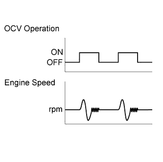
| Mass air flow meter malfunction |
| ||
| EGR valve does not close properly |
| ||
| The initial combustion and starter turnoff occur late | Engine coolant temperature sensor malfunction |
| 60 to 73 |
| Mass air flow meter malfunction |
| ||
| Abnormal A/F learning value |
| ||
| Deviation from fuel injection characteristics |
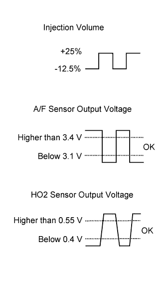
| ||
| Wet-fouled or dry-fouled spark plug |
| ||
| Lack of fuel pressure |
|
Systems to inspect.
| Troubleshooting by System | Suspected Area | Suspected Component | Procedure |
| Fuel system troubleshooting A | Abnormal A/F learning value |
| 89 to 96 97 to 104 |
| Rough idling |
| ||
| Abnormal fuel pressure |
| ||
| Fuel system troubleshooting B | Abnormal concentration of HC in surge tank |
| 105 to 107 |
| Fuel system troubleshooting C | Injection signal system malfunction |
| 75 to 79 |
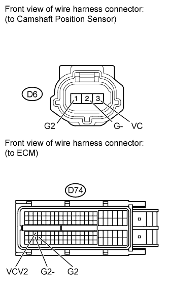
| Intake system troubleshooting | Difference between ISC target value and opening angle when idling |
| 86 to 88 108 to 110 |
| Ignition system troubleshooting | Camshaft and/or crankshaft position sensor signal malfunction |
| 80 to 85 111 to 116 |
| 1.CHECK ANY OTHER DTCS OUTPUT AND RECORD FREEZE FRAME DATA |
Connect the Techstream to the DLC3.
Turn the ignition switch to ON.
Enter the following menus: Powertrain / Engine and ECT / Trouble Codes.
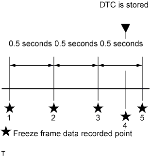 |
Read the DTCs and record the Freeze Frame Data.
| Result | Proceed to |
| Only DTC P1604 is output | A |
| DTCs other than P1604 are output | B |
|
| ||||
| A | |
 |
| 2.CHECK ENGINE IMMOBILISER SYSTEM |
Connect the Techstream to the DLC3.
Turn the ignition switch to ON.
Turn the Techstream on.
Enter the following menus: Powertrain / Engine and ECT / Data List / All Data / Immobiliser Fuel Cut.
Read the value displayed on the Techstream.
|
| ||||
| OK | |
|
| 3.CHECK MALFUNCTION CONDITION |
Confirm the problem symptoms.
| Result | Proceed to |
| Freeze frame data exists, but the starting difficulty cannot be reproduced and it is unknown what kind of starting difficulty occurred | A |
| The problem symptoms can be reproduced, or the malfunction conditions are known | B |
|
| ||||
| A | |
|
| 4.CHECK FREEZE FRAME DATA |
Connect the Techstream to the DLC3.
Turn the ignition switch to ON.
Using the Techstream, confirm the vehicle conditions recorded in the freeze frame data which were present when the DTC was stored (Click here).
| Freeze Frame Data Item | Suspected Area | Proceed to | |
| Engine Speed | Battery Voltage | ||
| All 5 sets of freeze frame data are 0 rpm (no engine cranking at all) | Minimum voltage is less than 5 V | Battery fully depleted | A |
| Minimum voltage is 5 V or higher |
| B | |
| 60 to 250 rpm (engine cranks but no initial combustion) | - |
| C |
| 250 rpm or higher (combustion occurs but initial combustion and starter turnoff occur late) | - |
| D |
|
| ||||
|
| ||||
|
| ||||
|
| ||||
| A | ||
 | ||
| ||
| 5.CHECK FREEZE FRAME DATA |
Connect the Techstream to the DLC3.
Turn the ignition switch to ON.
Using the Techstream, confirm the vehicle conditions recorded in the freeze frame data which were present when the DTC was stored (Click here).
| Freeze Frame Data Item | Result | Suspected Area | Proceed to |
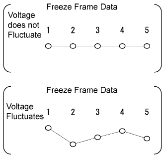
| Battery Voltage | Minimum voltage is 6 V or higher and voltage does not fluctuate*1 | Starter system | A |
| Minimum voltage is 6 V or higher and voltage fluctuates*2, *3 |
| B | |
| Minimum voltage is 5 to 6 V*4 |
| C |
 |
|
| ||||
|
| ||||
| A | ||
| ||
| ||
| 6.CHECK SENSOR INSTALLATION |
Check the tightening and installation condition of the crankshaft position sensor bolt.
Check the connection of the crankshaft position sensor connector.
| Result | Proceed to |
| Normal | A |
| Abnormal | B |
|
| ||||
| A | |
|
| 7.CHECK CRANKSHAFT POSITION SENSOR |
Disconnect the crankshaft position sensor connector.
Check for oil on the connector terminals.
|
| ||||
| OK | |
|
| 8.CHECK HARNESS AND CONNECTOR (CRANKSHAFT POSITION SENSOR - ECM) |
 |
Disconnect the crankshaft position sensor connector.
Disconnect the ECM connector.
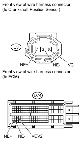
Measure the resistance according to the value(s) in the table below.
| Tester Connection | Condition | Specified Condition |
| D3-1 (NE+) - D74-110 (NE+) | Always | Below 1 Ω |
| D3-2 (NE-) - D74-111 (NE-) | Always | Below 1 Ω |
| D3-3 (VC) - D74-66 (VCV2) | Always | Below 1 Ω |
| D3-1 (NE+) or D74-110 (NE+) - Body ground | Always | 10 kΩ or higher |
| D3-2 (NE-) or D74-111 (NE-) - Body ground | Always | 10 kΩ or higher |
| D3-3 (VC) or D74-66 (VCV2) - Body ground | Always | 10 kΩ or higher |
|
| ||||
| OK | |
|
| 9.CHECK CRANKSHAFT POSITION SENSOR |
Replace the crankshaft position sensor (Click here).
Check the engine start operation.
|
| ||||
| OK | ||
| ||
| ||
| 10.CHECK FREEZE FRAME DATA |
Connect the Techstream to the DLC3.
Turn the ignition switch to ON.
Using the Techstream, confirm the vehicle conditions recorded in the freeze frame data which were present when the DTC was stored (Click here).
| Freeze Frame Data Item | Suspected Area | Proceed to | ||
| Coolant Temp, Ambient Temperature, Intake Air | Coolant Temp, Ambient Temperature | Fuel Pump Duty | ||
| Difference between Coolant Temp, Ambient Temperature and Intake Air is 10°C or more*1 | Coolant Temp is 125°C or more, or lower than Ambient Temperature by 15°C or more | - | Engine coolant temperature sensor | A |
| Other than above | All 5 sets of freeze frame data are except 0% | - | B | |
| At least 1 of the 5 sets of freeze frame data is 0% | Fuel pump control system | C | ||
| Difference between Coolant Temp, Ambient Temperature and Intake Air is less than 10°C*2 | - | At least 1 of the 5 sets of freeze frame data is 0% | Fuel pump control system | C |
| All 5 sets of freeze frame data are except 0% | - | B | ||
|
| ||||
|
| ||||
| A | ||
| ||
| ||
| 11.PERFORM ACTIVE TEST USING TECHSTREAM (CONTROL THE FUEL PUMP / SPEED) |
Connect the Techstream to the DLC3.
Turn the ignition switch to ON.
Using the Techstream, select the [Control the Fuel Pump / Speed] Active Test.
When performing the Active Test, check for an operating sound from the fuel pump.
| Control the Fuel Pump / Speed | Specified Condition |
| ON | Operating sound heard |
| OFF | Operating sound not heard |
|
| ||||
| OK | |
|
| 12.CHECK HARNESS AND CONNECTOR (FUEL INJECTOR POWER SOURCE) |
 |
Disconnect the injector connector.
Turn the ignition switch to ON.
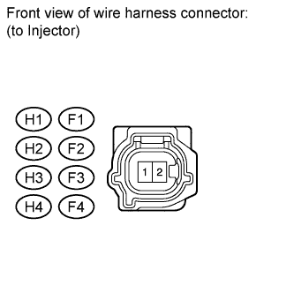
Measure the voltage according to the value(s) in the table below.
| Cylinder | Tester Connection | Switch Condition | Specified Condition |
| No. 1 | H1-2 - Ground | Ignition switch ON | 11 to 14 V |
| No. 2 | F1-2 - Ground | Ignition switch ON | 11 to 14 V |
| No. 3 | H2-2 - Ground | Ignition switch ON | 11 to 14 V |
| No. 4 | F2-2 - Ground | Ignition switch ON | 11 to 14 V |
| No. 5 | H3-2 - Ground | Ignition switch ON | 11 to 14 V |
| No. 6 | F3-2 - Ground | Ignition switch ON | 11 to 14 V |
| No. 7 | H4-2 - Ground | Ignition switch ON | 11 to 14 V |
| No. 8 | F4-2 - Ground | Ignition switch ON | 11 to 14 V |
|
| ||||
| OK | |
|
| 13.PERFORM ACTIVE TEST USING TECHSTREAM (CONTROL THE FUEL PUMP / SPEED) |
Connect the Techstream to the DLC3.
Turn the ignition switch to ON.
Using the Techstream, select the [Control the Fuel Pump / Speed] Active Test.
When performing the Active Test, check for fuel leakage from the fuel pipes.
| Result | Proceed to |
| Fuel leakage or signs of fuel leakage are present | A |
| No fuel leakage or signs of fuel leakage | B |
|
| ||||
| A | ||
| ||
| ||
| 14.CHECK FUEL SYSTEM |
Check for foreign matter such as iron particles around the fuel pump (fuel pump, fuel pump filter, and inside the fuel tank), and for signs that the fuel pump was stuck.
| Result | Proceed to |
| There is foreign matter or signs that fuel pump was stuck | A |
| There is no foreign matter and no signs that fuel pump was stuck | B |
|
| ||||
| A | ||
| ||
| ||
| 15.CHECK FREEZE FRAME DATA |
Connect the Techstream to the DLC3.
Turn the ignition switch to ON.
Using the Techstream, confirm the vehicle conditions recorded in the freeze frame data which were present when the DTC was stored (Click here).
| Freeze Frame Data Item | Suspected Area | Proceed to | |||
| Coolant Temp, Ambient Temperature, Intake Air | Coolant Temp, Ambient Temperature | Long FT | Engine Speed | ||
| Difference between Coolant Temp, Ambient Temperature and Intake Air is 10°C or more | Coolant Temp is 125°C or more, or lower than Ambient Temperature by 15°C or more | - | - | Engine coolant temperature sensor | A |
| Other than above | -15% or less, or +15% or more | - |
| B | |
| -15 to +15% | Minimum speed is 300 rpm or more*1 | Engine assembly | C | ||
| Minimum speed is below 300 rpm |
| D | |||
| Difference between Coolant Temp, Ambient Temperature and Intake Air is less than 10°C | - | -15% or less, or +15% or more | - |
| B |
| -15 to +15% | Minimum speed is 300 rpm or more*1 | Engine assembly | C | ||
| Minimum speed is below 300 rpm |
| D | |||
|
| ||||
|
| ||||
|
| ||||
| A | ||
| ||
| ||
| 16.INSPECT FUEL INJECTOR |
Check that no carbon is stuck to the fuel injector.
|
| ||||
| OK | |
|
| 17.CHECK FUEL SYSTEM |
Check for foreign matter such as iron particles around the fuel pump (fuel pump, fuel pump filter, and inside the fuel tank), and for signs that the fuel pump was stuck.
| Result | Proceed to |
| There is foreign matter or signs that fuel pump was stuck | A |
| There is no foreign matter and no signs that fuel pump was stuck | B |
|
| ||||
| A | ||
| ||
| ||
| 18.CHECK FREEZE FRAME DATA |
Connect the Techstream to the DLC3.
Turn the ignition switch to ON.
Using the Techstream, confirm the vehicle conditions recorded in the freeze frame data which were present when the DTC was stored (Click here).
| Freeze Frame Data Item | Result | Suspected Area | Proceed to |
| Coolant Temp | Engine coolant temperature is 40°C or less*1 | Pressure regulator | A |
| Engine coolant temperature is 40 to 90°C*2 | Fuel injector | B | |
| Engine coolant temperature is 90°C or more*3 | Pressure regulator | A |
|
| ||||
| A | |
|
| 19.CHECK FUEL PRESSURE |
Attach a fuel pressure gauge and check the fuel pressure after stopping the engine.
| Result | Proceed to |
| Normal | A |
| Abnormal | B |
|
| ||||
|
| ||||
| 20.CHECK FUEL INJECTOR |
Clean the inside of the surge tank with compressed air.
After stopping the engine, measure the HC concentration inside the surge tank for 15 minutes.
| Result | Proceed to |
| 4000 ppm or higher | A |
| Less than 4000 ppm | B |
|
| ||||
| A | |
|
| 21.CHECK FUEL INJECTOR |
Inspect the fuel injectors .
| Result | Proceed to |
| Abnormal | A |
| Normal | B |
|
| ||||
| A | ||
| ||
| ||
| 22.CHECK THROTTLE BODY |
Check if carbon is in the air flow passage.
| Result | Proceed to |
| Carbon in passage | A |
| No carbon present | B |
|
| ||||
| A | ||
| ||
| ||
| 23.CHECK INTAKE SYSTEM |
Check the intake system for vacuum leak .
|
| ||||
| OK | |
|
| 24.PERFORM SIMULATION TEST |
Check if the engine can be started.
| Result | Proceed to |
| Engine can be started | A |
| Engine cannot be started | B |
|
| ||||
| A | ||
| ||
| ||
| 25.CONFIRM PROBLEM SYMPTOM |
Confirm the problem symptoms.
| Problem Symptom | Suspected Area | Proceed to |
| The engine does not crank |
| A |
| Abnormal cranking speed |
| B |
| There is no initial combustion (combustion does not occur even once)*1 |
| C |
| The engine stalls after starter turnoff (engine stalls immediately after the first time the engine speed increases)*2 |
| D |
| The initial combustion and starter turnoff occur late*3 |
| E |
|
| ||||
|
| ||||
|
| ||||
|
| ||||
| A | |
|
| 26.PERFORM SIMULATION TEST |
When cranking the engine, check for a noise indicating that the starter pinion gear is extending, and check that the starter pinion gear is not spinning freely.
| Problem Symptom | Suspected Area | Proceed to |
| A noise indicating that the starter pinion gear is extending is heard and the starter pinion gear is not spinning freely.*1 |
| A |
| A noise indicating that the starter pinion gear is extending is heard but the starter pinion gear is spinning freely. |
| B |
| A noise indicating that the starter pinion gear is extending is not heard |
| C |
|
| ||||
|
| ||||
| A | |
|
| 27.INSPECT BATTERY |
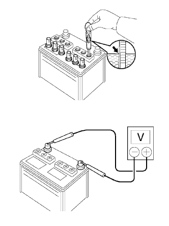 |
Check the electrolyte quantity.
Inspect the specific gravity.
Inspect the specific gravity of each cell.
Inspect the battery voltage.
Turn the ignition switch off and turn on the headlights for 20 to 30 seconds. This will remove the surface charge from the battery.
Measure the battery voltage.
Measure the battery voltage when cranking the engine.
|
| ||||
| OK | |
|
| 28.CHECK ENGINE ASSEMBLY |
Check that the crankshaft rotates smoothly when rotating it by hand.
|
| ||||
| OK | ||
| ||
| ||
| 29.CHECK STARTER |
Remove the starter (for 1.6 kW type) .
Remove the starter (for 2.0 kW type) .
Check for starter pinion gear wear and damage.
|
| ||||
| OK | ||
| ||
| ||
| 30.INSPECT BATTERY |
|
Check the electrolyte quantity.
Inspect the specific gravity.
Inspect the specific gravity of each cell.
Inspect the battery voltage.
Turn the ignition switch off and turn on the headlights for 20 to 30 seconds. This will remove the surface charge from the battery.
Measure the battery voltage.
Measure the battery voltage when cranking the engine.
|
| ||||
| OK | |
|
| 31.INSPECT STARTER |
Inspect the starter (for 1.6 kW type) .
Inspect the starter (for 2.0 kW type) .
|
| ||||
| OK | ||
| ||
| ||
| 32.PERFORM SIMULATION TEST |
Check the cranking speed.
| Problem Symptom | Suspected Area | Proceed to |
| Cranking speed is slow (100 rpm or less) |
| A |
| Cranking speed is fast (300 rpm or more)*1 | Engine compression loss | B |
|
| ||||
| A | |
|
| 33.INSPECT BATTERY |
|
Check the electrolyte quantity.
Inspect the specific gravity.
Inspect the specific gravity of each cell.
Inspect the battery voltage.
Turn the ignition switch off and turn on the headlights for 20 to 30 seconds. This will remove the surface charge from the battery.
Measure the battery voltage.
Measure the battery voltage when cranking the engine.
|
| ||||
| OK | |
|
| 34.CHECK ENGINE |
Check that the crankshaft rotates smoothly when rotating it by hand.
|
| ||||
| OK | ||
| ||
| ||
| 35.CHECK FUEL INJECTOR |
Using a sound scope or screwdriver, check for an injector operating noise while cranking the engine.
|
| ||||
| OK | |
|
| 36.CHECK FUEL PRESSURE |
Inspect the fuel pressure .
|
| ||||
| OK | |
|
| 37.CHECK SPARK PLUG AND SPARK |
Check for sparks .
|
| ||||
| OK | |
|
| 38.CONFIRM VEHICLE CONDITION |
Confirm the conditions present when the malfunction occurred based on the customer problem analysis.
| Problem Symptom | Suspected Area | Proceed to |
| When the engine is stopped and a long time has passed, engine starting trouble occurs*1 | Pressure regulator is stuck open | A |
| When the engine is stopped and approximately 15 to 120 minutes have passed, engine starting trouble occurs*2 | Fuel injector leak | B |
| When the engine is stopped and approximately 2 to 3 minutes have passed, engine starting trouble occurs*3 | Failure to maintain fuel pressure by pressure regulator | A |
| Condition other than above, or there is an inconsistency in the conditions present when engine starting trouble occurs | - | C*4 |
|
| ||||
|
| ||||
| A | |
|
| 39.CHECK FUEL PRESSURE |
Attach a fuel pressure gauge and check the fuel pressure after stopping the engine.
| Result | Proceed to |
| 147 kPa (1.5 kgf/cm2) or higher (5 minutes after stopping the engine) | A*1 |
| Less than 147 kPa (1.5 kgf/cm2) (5 minutes after stopping the engine) | B |
|
| ||||
|
| ||||
| 40.CHECK FUEL INJECTOR |
After stopping the engine, measure the HC concentration inside the surge tank for 15 minutes.
| Result | Proceed to |
| 4000 ppm or higher | A |
| Less than 4000 ppm | B*1 |
|
| ||||
| A | ||
| ||
| ||
| 41.CHECK SPARK PLUG |
Inspect the spark plugs .
|
| ||||
| OK | |
|
| 42.READ VALUE USING TECHSTREAM (ENGINE SPEED) |
Connect the Techstream to the DLC3.
Turn the ignition switch to ON.
Using the Techstream, select [Engine Speed] of the Data List.
Start the engine.
While running the engine, read the [Engine Speed] value.
|
| ||||
| OK | |
|
| 43.CHECK HARNESS AND CONNECTOR (IGNITION COIL POWER SOURCE) |
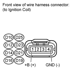 |
Disconnect the ignition coil connector.
Turn the ignition switch to ON.
Measure the voltage according to the value(s) in the table below.
| Tester Connection | Switch Condition | Specified Condition |
| D10-1 (+B) - D10-4 (GND) | Ignition switch ON | 11 to 14 V |
| D25-1 (+B) - D25-4 (GND) | Ignition switch ON | 11 to 14 V |
| D12-1 (+B) - D12-4 (GND) | Ignition switch ON | 11 to 14 V |
| D23-1 (+B) - D23-4 (GND) | Ignition switch ON | 11 to 14 V |
| D14-1 (+B) - D14-4 (GND) | Ignition switch ON | 11 to 14 V |
| D21-1 (+B) - D21-4 (GND) | Ignition switch ON | 11 to 14 V |
| D16-1 (+B) - D16-4 (GND) | Ignition switch ON | 11 to 14 V |
| D19-1 (+B) - D19-4 (GND) | Ignition switch ON | 11 to 14 V |
|
| ||||
| OK | |
|
| 44.CHECK HARNESS AND CONNECTOR (IGNITION COIL - ECM) |
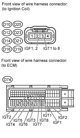 |
Disconnect the ignition coil connector.
Disconnect the ECM connector.
Measure the resistance according to the value(s) in the table below.
| Tester Connection | Condition | Specified Condition |
| D10-2 (IGF1) - D74-104 (IGF1) | Always | Below 1 Ω |
| D25-2 (IGF2) - D74-105 (IGF2) | Always | Below 1 Ω |
| D12-2 (IGF2) - D74-105 (IGF2) | Always | Below 1 Ω |
| D23-2 (IGF1) - D74-104 (IGF1) | Always | Below 1 Ω |
| D14-2 (IGF2) - D74-105 (IGF2) | Always | Below 1 Ω |
| D21-2 (IGF1) - D74-104 (IGF1) | Always | Below 1 Ω |
| D16-2 (IGF1) - D74-104 (IGF1) | Always | Below 1 Ω |
| D19-2 (IGF2) - D74-105 (IGF2) | Always | Below 1 Ω |
| D10-2 (IGF1) or D74-104 (IGF1) - Body ground | Always | 10 kΩ or higher |
| D25-2 (IGF2) or D74-105 (IGF2) - Body ground | Always | 10 kΩ or higher |
| D12-2 (IGF2) or D74-105 (IGF2) - Body ground | Always | 10 kΩ or higher |
| D23-2 (IGF1) or D74-104 (IGF1) - Body ground | Always | 10 kΩ or higher |
| D14-2 (IGF2) or D74-105 (IGF2) - Body ground | Always | 10 kΩ or higher |
| D21-2 (IGF1) or D74-104 (IGF1) - Body ground | Always | 10 kΩ or higher |
| D16-2 (IGF1) or D74-104 (IGF1) - Body ground | Always | 10 kΩ or higher |
| D19-2 (IGF2) or D74-105 (IGF2) - Body ground | Always | 10 kΩ or higher |
|
| ||||
| OK | |
|
| 45.CHECK HARNESS AND CONNECTOR (IGNITION COIL - ECM) |
|
Disconnect the ignition coil connector.
Disconnect the ECM connector.
Measure the resistance according to the value(s) in the table below.
| Tester Connection | Condition | Specified Condition |
| D10-3 (IGT1) - D74-40 (IGT1) | Always | Below 1 Ω |
| D25-3 (IGT2) - D74-33 (IGT2) | Always | Below 1 Ω |
| D12-3 (IGT3) - D74-37 (IGT3) | Always | Below 1 Ω |
| D23-3 (IGT4) - D74-34 (IGT4) | Always | Below 1 Ω |
| D14-3 (IGT5) - D74-35 (IGT5) | Always | Below 1 Ω |
| D21-3 (IGT6) - D74-36 (IGT6) | Always | Below 1 Ω |
| D16-3 (IGT7) - D74-38 (IGT7) | Always | Below 1 Ω |
| D19-3 (IGT8) - D74-39 (IGT8) | Always | Below 1 Ω |
| D10-3 (IGT1) or D74-40 (IGT1) - Body ground | Always | 10 kΩ or higher |
| D25-3 (IGT2) or D74-33 (IGT2) - Body ground | Always | 10 kΩ or higher |
| D12-3 (IGT3) or D74-37 (IGT3) - Body ground | Always | 10 kΩ or higher |
| D23-3 (IGT4) or D74-34 (IGT4) - Body ground | Always | 10 kΩ or higher |
| D14-3 (IGT5) or D74-35 (IGT5) - Body ground | Always | 10 kΩ or higher |
| D21-3 (IGT6) or D74-36 (IGT6) - Body ground | Always | 10 kΩ or higher |
| D16-3 (IGT7) or D74-38 (IGT7) - Body ground | Always | 10 kΩ or higher |
| D19-3 (IGT8) or D74-39 (IGT8) - Body ground | Always | 10 kΩ or higher |
|
| ||||
| OK | ||
| ||
| ||
| 46.PERFORM ACTIVE TEST USING TECHSTREAM (CONTROL THE FUEL PUMP / SPEED) |
Connect the Techstream to the DLC3.
Turn the ignition switch to ON.
Using the Techstream, select the [Control the Fuel Pump / Speed] Active Test.
When performing the Active Test, check for an operating sound from the fuel pump.
| Control the Fuel Pump / Speed | Specified Condition |
| ON | Operating sound heard |
| OFF | Operating sound not heard |
|
| ||||
| OK | |
|
| 47.PERFORM ACTIVE TEST USING TECHSTREAM (CONTROL THE FUEL PUMP / SPEED) |
Connect the Techstream to the DLC3.
Turn the ignition switch to ON.
Using the Techstream, select the [Control the Fuel Pump / Speed] Active Test.
When performing the Active Test, check for fuel leakage from the fuel pipes.
| Result | Proceed to |
| Fuel leakage or signs of fuel leakage are present | A |
| No fuel leakage or signs of fuel leakage | B |
|
| ||||
| A | ||
| ||
| ||
| 48.READ VALUE USING TECHSTREAM (ENGINE SPEED) |
Connect the Techstream to the DLC3.
Turn the ignition switch to ON.
Using the Techstream, select [Engine Speed] of the Data List.
Start the engine.
While running the engine, read the [Engine Speed] value.
|
| ||||
| OK | |
|
| 49.CHECK HARNESS AND CONNECTOR (FUEL INJECTOR POWER SOURCE) |
|
Disconnect the injector connector.
Turn the ignition switch to ON.
Measure the voltage according to the value(s) in the table below.
| Cylinder | Tester Connection | Switch Condition | Specified Condition |
| No. 1 | H1-2 - Ground | Ignition switch ON | 11 to 14 V |
| No. 2 | F1-2 - Ground | Ignition switch ON | 11 to 14 V |
| No. 3 | H2-2 - Ground | Ignition switch ON | 11 to 14 V |
| No. 4 | F2-2 - Ground | Ignition switch ON | 11 to 14 V |
| No. 5 | H3-2 - Ground | Ignition switch ON | 11 to 14 V |
| No. 6 | F3-2 - Ground | Ignition switch ON | 11 to 14 V |
| No. 7 | H4-2 - Ground | Ignition switch ON | 11 to 14 V |
| No. 8 | F4-2 - Ground | Ignition switch ON | 11 to 14 V |
|
| ||||
| OK | |
|
| 50.CHECK HARNESS AND CONNECTOR (FUEL INJECTOR - ECM) |
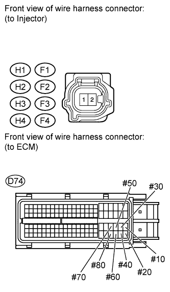 |
Disconnect the injector connector.
Disconnect the ECM connector.
Measure the resistance according to the value(s) in the table below.
| Cylinder | Tester Connection | Condition | Specified Condition |
| No. 1 | H1-1 - Ground | Always | 10 kΩ or higher |
| H1-1 - D74-86 (#10) | Always | Below 1 Ω | |
| No. 2 | F1-1 - Ground | Always | 10 kΩ or higher |
| F1-1 - D74-109 (#20) | Always | Below 1 Ω | |
| No. 3 | H2-1 - Ground | Always | 10 kΩ or higher |
| H2-1 - D74-85 (#30) | Always | Below 1 Ω | |
| No. 4 | F2-1 - Ground | Always | 10 kΩ or higher |
| F2-1 - D74-108 (#40) | Always | Below 1 Ω | |
| No. 5 | H3-1 - Ground | Always | 10 kΩ or higher |
| H3-1 - D74-84 (#50) | Always | Below 1 Ω | |
| No. 6 | F3-1 - Ground | Always | 10 kΩ or higher |
| F3-1 - D74-107 (#60) | Always | Below 1 Ω | |
| No. 7 | H4-1 - Ground | Always | 10 kΩ or higher |
| H4-1 - D74-83 (#70) | Always | Below 1 Ω | |
| No. 8 | F4-1 - Ground | Always | 10 kΩ or higher |
| F4-1 - D74-106 (#80) | Always | Below 1 Ω |
|
| ||||
| OK | ||
| ||
| ||
| 51.CHECK MASS AIR FLOW METER |
Connect the Techstream to the DLC3.
Start the engine and warm it up until the engine coolant temperature reaches 75°C (167°F) or higher.
Turn the Techstream on.
Enter the following menus: Powertrain / Engine and ECT / Data List / MAF.
Check MAF in the Data List during idling.
|
| ||||
| OK | |
|
| 52.CHECK INTAKE SYSTEM |
Check for air leakage in the intake system [vacuum hose disconnection, cracks, damaged gaskets, etc.] .
|
| ||||
| OK | |
|
| 53.CHECK THROTTLE BODY |
Disconnect the throttle body connector.
Crank the engine and check that it starts.
| Result | Proceed to |
| Engine starts | A |
| Engine does not start | B |
Connect the throttle body connector.
|
| ||||
| A | |
|
| 54.CHECK THROTTLE BODY |
Check if carbon is in the air flow passage.
|
| ||||
| OK | |
|
| 55.PERFORM ACTIVE TEST USING TECHSTREAM (CONTROL THE VVT SYSTEM) |
 |
Connect the Techstream to the DLC3.
Turn the Techstream on.
Warm up the engine.
Enter the following menus: Powertrain / Engine and ECT / Active Test / Control the VVT System (Bank 1) or Control the VVT System (Bank 2).
Check the engine speed while operating the Oil Control Valve (OCV) using the Techstream.
| Tester Operation | Specified Condition |
| OFF | Normal engine speed |
| ON | Soon after OCV switched from OFF to ON, engine idles roughly or stalls |
| Result | Proceed to |
| NG | A |
| OK | B |
|
| ||||
| A | ||
| ||
| ||
| 56.PERFORM ACTIVE TEST USING TECHSTREAM (CONTROL THE VVT EXHAUST LINEAR) |
Connect the Techstream to the DLC3.
Turn the Techstream on.
Warm up the engine.
Enter the following menus: Powertrain / Engine and ECT / Active Test / Control the VVT Exhaust Linear (Bank1) or Control the VVT Exhaust Linear (Bank2).
Check the engine speed while operating the Oil Control Valve (OCV) using the Techstream.
| Tester Operation | Specified Condition |
| 0% | Normal engine speed |
| 100% | Engine idles roughly or stalls |
|
| ||||
| OK | |
|
| 57.PERFORM ACTIVE TEST USING TECHSTREAM (CONTROL THE EGR STEP POSITION) |
Connect the Techstream to the DLC3.
Start the engine and warm it up until the engine coolant temperature reaches 75°C (167°F) or higher.
Turn the Techstream on.
Enter the following menus: Powertrain / Engine and ECT / Active Test / Control the EGR Step Position.
Confirm the Throttle Idle Position is ON and check the engine idling condition and MAP values in the Data List while performing the Active Test.
| - | EGR Step Position (Active Test) | |
| 0 Steps | 0 to 30 Steps | |
| Idling condition | Steady idling | Idling changes from steady to rough idling or engine stall |
| MAP (Data List) | 20 to 40 kPa (150 to 300 mmHg) | MAP value is at least +10 kPa (75 mmHg) higher than when EGR valve is fully closed |
|
| ||||
|
| ||||
| 58.INSPECT EGR VALVE |
Remove the EGR valve assembly (Click here).
Check if the EGR valve assembly is stuck open.
|
| ||||
|
| ||||
| 59.CHECK HARNESS AND CONNECTOR (MASS AIR FLOW METER - ECM) |
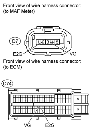 |
Disconnect the MAF meter connector.
Disconnect the ECM connector.
Measure the resistance according to the value(s) in the table below.
| Tester Connection | Condition | Specified Condition |
| D7-3 (VG) - D74-74 (VG) | Always | Below 1 Ω |
| D7-2 (E2G) - D74-75 (E2G) | Always | Below 1 Ω |
| D7-3 (VG) or D74-74 (VG) - Body ground | Always | 10 kΩ or higher |
|
| ||||
| OK | ||
| ||
| ||
| 60.INSPECT ENGINE COOLANT TEMPERATURE SENSOR |
Inspect the engine coolant temperature sensor .
|
| ||||
| OK | |
|
| 61.CHECK HARNESS AND CONNECTOR (ENGINE COOLANT TEMPERATURE SENSOR - ECM) |
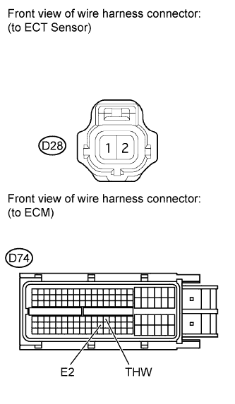 |
Disconnect the ECT sensor connector.
Disconnect the ECM connector.
Measure the resistance according to the value(s) in the table below.
| Tester Connection | Condition | Specified Condition |
| D28-2 - D74-76 (THW) | Always | Below 1 Ω |
| D28-1 - D74-98 (E2) | Always | Below 1 Ω |
| D28-2 or D74-76 (THW) - Body ground | Always | 10 kΩ or higher |
| D28-1 or D74-98 (E2) - Body ground | Always | 10 kΩ or higher |
|
| ||||
| OK | |
|
| 62.CHECK MASS AIR FLOW METER |
Connect the Techstream to the DLC3.
Start the engine and warm it up until the engine coolant temperature reaches 75°C (167°F) or higher.
Turn the Techstream on.
Enter the following menus: Powertrain / Engine and ECT / Data List / MAF.
Check MAF in the Data List during idling.
|
| ||||
| OK | |
|
| 63.CHECK HARNESS AND CONNECTOR (MASS AIR FLOW METER - ECM) |
|
Disconnect the MAF meter connector.
Disconnect the ECM connector.
Measure the resistance according to the value(s) in the table below.
| Tester Connection | Condition | Specified Condition |
| D7-3 (VG) - D74-74 (VG) | Always | Below 1 Ω |
| D7-2 (E2G) - D74-75 (E2G) | Always | Below 1 Ω |
| D7-3 (VG) or D74-74 (VG) - Body ground | Always | 10 kΩ or higher |
|
| ||||
| OK | |
|
| 64.READ VALUE USING TECHSTREAM |
Connect the Techstream to the DLC3.
Turn the ignition switch to ON.
Using the Techstream, select and read [Long FT] and [Atmosphere Pressure] in the Data List.
| Data List Item | Result | Suspected Area | Proceed to |
| Long FT | +25% or more or less than -25% |
| A |
| Atmosphere Pressure | 80 kPa or less (when altitude is 0 m) | ||
| Both Data List items listed above | Values are other than above | - | B |
|
| ||||
| A | |
|
| 65.PERFORM SIMULATION TEST |
Remove the EFI NO. 1 and ETCS fuses from the engine room relay block.
After 60 seconds or more elapse, install the EFI NO. 1 and ETCS fuses.
Check if the engine can be started.
| Result | Proceed to |
| Engine can be started | A |
| Engine cannot be started | B |
|
| ||||
| A | |
|
| 66.INSPECT AIR FUEL RATIO SENSOR |
 |
Connect the Techstream to the DLC3.
Start the engine.
Turn the Techstream on.
Enter the following menus: Powertrain / Engine and ECT / Data List / Fuel System Status #1 and Fuel System Status #2.
Confirm that Fuel System Status #1 and Fuel System Status #2 are both CL.
Enter the following menus: Powertrain / Engine and ECT / Data List / AF Lambda B1S1 and AF Lambda B2S1.
Confirm that AF Lambda B1S1 and AF Lambda B2S1 are both within the range of 0.95 to 1.05 when idling.
Enter the following menus: Powertrain / Engine and ECT / Active Test / Control the Injection Volume for A/F sensor.
Read the output voltage from the air fuel ratio sensor when increasing and decreasing the fuel injection volume.
| Tester Display | Injection Volume | Specified Condition |
| AFS Voltage B1S1 AFS Voltage B2S1 | +25% | Air fuel ratio sensor output voltage is below 3.1 V |
| -12.5% | Air fuel ratio sensor output voltage is higher than 3.4 V |
| Result | Proceed to |
| Normal | A |
| Abnormal | B |
|
| ||||
| A | |
|
| 67.PERFORM SIMULATION TEST |
Check if the idling speed is stable after starting the engine.
|
| ||||
| OK | ||
| ||
| ||
| 68.CHECK FUEL PRESSURE |
Inspect the fuel pressure .
|
| ||||
| OK | |
|
| 69.CHECK SPARK PLUG |
Inspect the spark plugs .
| Result | Proceed to |
| All cylinders are normal | A |
| One cylinder is abnormal*1 | B |
| All cylinders are abnormal*2, *3 | C |
|
| ||||
|
| ||||
| A | |
|
| 70.CONFIRM VEHICLE CONDITION |
Confirm the conditions present when the malfunction occurred based on the customer problem analysis.
| Problem Symptom | Suspected Area | Proceed to |
| When the engine is stopped and a long time has passed, engine starting trouble occurs*1 | Pressure regulator is stuck open | A |
| When the engine is stopped and approximately 15 to 120 minutes have passed, engine starting trouble occurs*2 | Fuel injector leak | B |
| When the engine is stopped and approximately 2 to 3 minutes have passed, engine starting trouble occurs*3 | Failure to maintain fuel pressure by pressure regulator | A |
| Condition other than above, or there is an inconsistency in the conditions present when engine starting trouble occurs | - | C*4 |
|
| ||||
|
| ||||
| A | |
|
| 71.CHECK FUEL PRESSURE |
Attach a fuel pressure gauge and check the fuel pressure after stopping the engine.
| Result | Proceed to |
| 147 kPa (1.5 kgf/cm2) or higher (5 minutes after stopping the engine) | A*1 |
| Less than 147 kPa (1.5 kgf/cm2) (5 minutes after stopping the engine) | B |
|
| ||||
|
| ||||
| 72.CHECK FUEL INJECTOR |
Clean the inside of the surge tank with compressed air.
After stopping the engine, measure the HC concentration inside the surge tank for 15 minutes.
| Result | Proceed to |
| 4000 ppm or higher | A |
| Less than 4000 ppm | B*1 |
|
| ||||
| A | ||
| ||
| ||
| 73.PERFORM ACTIVE TEST USING TECHSTREAM (CONTROL THE FUEL PUMP / SPEED) |
Connect the Techstream to the DLC3.
Turn the ignition switch to ON.
Using the Techstream, select the [Control the Fuel Pump / Speed] Active Test.
When performing the Active Test, check for fuel leakage from the fuel pipes.
| Result | Proceed to |
| Fuel leakage or signs of fuel leakage are present | A |
| No fuel leakage or signs of fuel leakage | B |
|
| ||||
| A | ||
| ||
| ||
| 74.CHECK MALFUNCTION CONDITION |
If the malfunction could not be identified during the inspection in steps 38, 39, 40 and 47, perform fuel system troubleshooting C (steps 75 to 79).
| Performed Step | Troubleshooting by System | Procedure | Proceed to |
| Steps 38, 39, 40 and 47 | Fuel system troubleshooting C | 75 to 79 | A |
If the malfunction could not be identified during the inspection in step 45, perform ignition system troubleshooting (steps 80 to 85).
| Performed Step | Troubleshooting by System | Procedure | Proceed to |
| Step 45 | Ignition system troubleshooting | 80 to 85 | B |
If the malfunction could not be identified during the inspection in steps 55, 56, 57, 58 and 59, perform intake air system troubleshooting (steps 86 to 88). If engine starting trouble still occurs, perform fuel system troubleshooting A (steps 89 to 96).
| Performed Step | Troubleshooting by System | Procedure | Proceed to |
| Step 55, 56, 57, 58, 59 | Intake air system troubleshooting | 86 to 88 | C |
| Fuel system troubleshooting A | 89 to 96 |
If the malfunction could not be identified during the inspection in steps 60, 61, 62, 63, 66, 67, 69, 70, 71, 72 and 73, perform fuel system troubleshooting A (steps 97 to 104), fuel system troubleshooting B (steps 105 to 107), intake air system troubleshooting (steps 108 to 110), and ignition system troubleshooting (steps 111 to 116), in that order.
| Performed Step | Troubleshooting by System | Procedure | Proceed to |
| Steps 60, 61, 62, 63, 66, 67, 69, 70, 71, 72 and 73 | Fuel system troubleshooting A | 97 to 104 | D |
| Fuel system troubleshooting B | 105 to 107 | ||
| Intake air system troubleshooting | 108 to 110 | ||
| Ignition system troubleshooting | 111 to 116 |
|
| ||||
|
| ||||
|
| ||||
| A | |
|
| 75.INSPECT FUEL INJECTOR |
Inspect the fuel injectors .
|
| ||||
| OK | |
|
| 76.CHECK HARNESS AND CONNECTOR (FUEL INJECTOR POWER SOURCE) |
|
Disconnect the injector connector.
Turn the ignition switch to ON.
Measure the voltage according to the value(s) in the table below.
| Cylinder | Tester Connection | Switch Condition | Specified Condition |
| No. 1 | H1-2 - Ground | Ignition switch ON | 11 to 14 V |
| No. 2 | F1-2 - Ground | Ignition switch ON | 11 to 14 V |
| No. 3 | H2-2 - Ground | Ignition switch ON | 11 to 14 V |
| No. 4 | F2-2 - Ground | Ignition switch ON | 11 to 14 V |
| No. 5 | H3-2 - Ground | Ignition switch ON | 11 to 14 V |
| No. 6 | F3-2 - Ground | Ignition switch ON | 11 to 14 V |
| No. 7 | H4-2 - Ground | Ignition switch ON | 11 to 14 V |
| No. 8 | F4-2 - Ground | Ignition switch ON | 11 to 14 V |
|
| ||||
| OK | |
|
| 77.CHECK HARNESS AND CONNECTOR (FUEL INJECTOR - ECM) |
|
Disconnect the injector connector.
Disconnect the ECM connector.
Measure the resistance according to the value(s) in the table below.
| Cylinder | Tester Connection | Condition | Specified Condition |
| No. 1 | H1-1 - Ground | Always | 10 kΩ or higher |
| H1-1 - D74-86 (#10) | Always | Below 1 Ω | |
| No. 2 | F1-1 - Ground | Always | 10 kΩ or higher |
| F1-1 - D74-109 (#20) | Always | Below 1 Ω | |
| No. 3 | H2-1 - Ground | Always | 10 kΩ or higher |
| H2-1 - D74-85 (#30) | Always | Below 1 Ω | |
| No. 4 | F2-1 - Ground | Always | 10 kΩ or higher |
| F2-1 - D74-108 (#40) | Always | Below 1 Ω | |
| No. 5 | H3-1 - Ground | Always | 10 kΩ or higher |
| H3-1 - D74-84 (#50) | Always | Below 1 Ω | |
| No. 6 | F3-1 - Ground | Always | 10 kΩ or higher |
| F3-1 - D74-107 (#60) | Always | Below 1 Ω | |
| No. 7 | H4-1 - Ground | Always | 10 kΩ or higher |
| H4-1 - D74-83 (#70) | Always | Below 1 Ω | |
| No. 8 | F4-1 - Ground | Always | 10 kΩ or higher |
| F4-1 - D74-106 (#80) | Always | Below 1 Ω |
|
| ||||
| OK | |
|
| 78.CHECK CRANKSHAFT POSITION SENSOR |
Replace the crankshaft position sensor (Click here).
Check the engine start operation.
|
| ||||
| OK | ||
| ||
| ||
| 79.CHECK CAMSHAFT POSITION SENSOR |
Replace the camshaft position sensor (Click here).
Check the engine start operation.
|
| ||||
| OK | ||
| ||
| ||
| 80.CHECK CRANKSHAFT POSITION SENSOR |
Check the tightening and installation condition of the crankshaft position sensor bolt.
Check the connection of the crankshaft position sensor connector.
|
| ||||
| OK | |
|
| 81.CHECK CAMSHAFT POSITION SENSOR |
Check the tightening and installation condition of the camshaft position sensor bolt.
Check the connection of the camshaft position sensor connector.
|
| ||||
| OK | |
|
| 82.CHECK HARNESS AND CONNECTOR (CRANKSHAFT POSITION SENSOR - ECM) |
|
Disconnect the crankshaft position sensor connector.
Disconnect the ECM connector.
Measure the resistance according to the value(s) in the table below.
| Tester Connection | Condition | Specified Condition |
| D3-1 (NE+) - D74-110 (NE+) | Always | Below 1 Ω |
| D3-2 (NE-) - D74-111 (NE-) | Always | Below 1 Ω |
| D3-3 (VC) - D74-66 (VCV2) | Always | Below 1 Ω |
| D3-1 (NE+) or D74-110 (NE+) - Body ground | Always | 10 kΩ or higher |
| D3-2 (NE-) or D74-111 (NE-) - Body ground | Always | 10 kΩ or higher |
| D3-3 (VC) or D74-66 (VCV2) - Body ground | Always | 10 kΩ or higher |
|
| ||||
| OK | |
|
| 83.CHECK HARNESS AND CONNECTOR (CAMSHAFT POSITION SENSOR - ECM) |
 |
Disconnect the camshaft position sensor connector.
Disconnect the ECM connector.
Measure the resistance according to the value(s) in the table below.
| Tester Connection | Condition | Specified Condition |
| D6-1 (G2) - D74-90 (G2) | Always | Below 1 Ω |
| D6-2 (G-) - D74-89 (G2-) | Always | Below 1 Ω |
| D6-3 (VC) - D74-66 (VCV2) | Always | Below 1 Ω |
| D6-1 (G2) or D74-90 (G2) - Body ground | Always | 10 kΩ or higher |
| D6-2 (G-) or D74-89 (G2-) - Body ground | Always | 10 kΩ or higher |
| D6-3 (VC) or D74-66 (VCV2) - Body ground | Always | 10 kΩ or higher |
|
| ||||
| OK | |
|
| 84.CHECK CRANKSHAFT POSITION SENSOR |
Replace the crankshaft position sensor (Click here).
Check the engine start operation.
|
| ||||
| OK | ||
| ||
| ||
| 85.CHECK CAMSHAFT POSITION SENSOR |
Replace the camshaft position sensor (Click here).
Check the engine start operation.
|
| ||||
| OK | ||
| ||
| ||
| 86.READ VALUE USING TECHSTREAM (ISC LEARNING VALUE) |
Connect the Techstream to the DLC3.
Turn the ignition switch to ON.
Start the engine and warm it up until the engine coolant temperature stabilizes with the A/C switch and all the accessory switches should be off
Using the Techstream, select and read [ISC Learning Value] in the Data List.
| Data List Item | Result | Suspected Area | Proceed to |
| ISC Learning Value | (engine displacement (liters) x 0.9) or more |
| A |
| Less than (engine displacement (liters) x 0.9) | - | B |
|
| ||||
| A | |
|
| 87.CHECK CYLINDER COMPRESSION PRESSURE |
Inspect the compression .
|
| ||||
| OK | ||
| ||
| ||
| 88.INSPECT ENGINE COOLANT TEMPERATURE SENSOR |
Inspect the engine coolant temperature sensor .
|
| ||||
| OK | |
|
| 89.CHECK FUEL PRESSURE |
Attach a fuel pressure gauge and check the fuel pressure when cranking the engine and after stopping the engine.
| Vehicle State | Specified Condition |
| Cranking engine | 304 to 343 kPa (3.1 to 3.5 kgf/cm2) |
| 5 minutes after stopping engine | 147 kPa (1.5 kgf/cm2) or more |
|
| ||||
| OK | |
|
| 90.READ VALUE USING TECHSTREAM (LONG FT) |
Connect the Techstream to the DLC3.
Turn the ignition switch to ON.
Using the Techstream, select and read [Long FT] in the Data List.
| Data List Item | Result | Suspected Area | Proceed to |
| Long FT | -15 to +15% |
| A |
| +15% or more, or less than -15% | Fuel injector | B |
|
| ||||
| A | |
|
| 91.PERFORM SIMULATION TEST |
Check if the idling speed after starting the engine is currently stable and has always been stable in the past.
| Problem Symptom | Suspected Area | Proceed to |
| Current unstable idling speed or history of unstable idling speed | Crankshaft position sensor system | A |
| All current and past idling speeds are stable | Fuel | B |
|
| ||||
| A | |
|
| 92.CHECK CRANKSHAFT POSITION SENSOR |
Check the tightening and installation condition of the crankshaft position sensor bolt.
Check the connection of the crankshaft position sensor connector.
|
| ||||
| OK | |
|
| 93.CHECK HARNESS AND CONNECTOR (CRANKSHAFT POSITION SENSOR - ECM) |
|
Disconnect the crankshaft position sensor connector.
Disconnect the ECM connector.
Measure the resistance according to the value(s) in the table below.
| Tester Connection | Condition | Specified Condition |
| D3-1 (NE+) - D74-110 (NE+) | Always | Below 1 Ω |
| D3-2 (NE-) - D74-111 (NE-) | Always | Below 1 Ω |
| D3-3 (VC) - D74-66 (VCV2) | Always | Below 1 Ω |
| D3-1 (NE+) or D74-110 (NE+) - Body ground | Always | 10 kΩ or higher |
| D3-2 (NE-) or D74-111 (NE-) - Body ground | Always | 10 kΩ or higher |
| D3-3 (VC) or D74-66 (VCV2) - Body ground | Always | 10 kΩ or higher |
|
| ||||
| OK | |
|
| 94.CHECK CRANKSHAFT POSITION SENSOR |
Replace the crankshaft position sensor (Click here).
Check the engine start operation.
|
| ||||
| OK | ||
| ||
| ||
| 95.PERFORM ACTIVE TEST USING TECHSTREAM (CONTROL THE FUEL PUMP / SPEED) |
Connect the Techstream to the DLC3.
Turn the ignition switch to ON.
Using the Techstream, select the [Control the Fuel Pump / Speed] Active Test.
When performing the Active Test, check for fuel leakage from the fuel pipes.
| Result | Proceed to |
| Fuel leakage or signs of fuel leakage are present | A |
| No fuel leakage or signs of fuel leakage | B |
|
| ||||
| A | ||
| ||
| ||
| 96.INSPECT FUEL PUMP |
Remove the fuel suction tube.
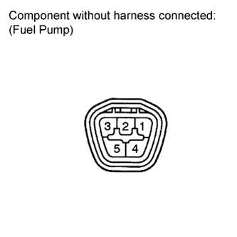 |
Measure the resistance according to the value(s) in the table below.
| Tester Connection | Condition | Specified Condition |
| 4 - 5 | 20°C | 0.2 to 3.0 Ω |
|
| ||||
| OK | ||
| ||
| ||
| 97.CHECK FUEL PRESSURE |
Attach a fuel pressure gauge and check the fuel pressure after stopping the engine.
| Result | Proceed to |
| 147 kPa (1.5 kgf/cm2) or higher (5 minutes after stopping the engine) | A |
| Less than 147 kPa (1.5 kgf/cm2) (5 minutes after stopping the engine) | B |
|
| ||||
| A | |
|
| 98.READ VALUE USING TECHSTREAM (LONG FT) |
Connect the Techstream to the DLC3.
Turn the ignition switch to ON.
Using the Techstream, select and read [Long FT] in the Data List.
| Data List Item | Result | Suspected Area | Proceed to |
| Long FT | -15 to +15% |
| A |
| +15% or more, or less than -15% | Fuel injector | B |
|
| ||||
| A | |
|
| 99.PERFORM SIMULATION TEST |
Check if the idling speed after starting the engine is currently stable and has always been stable in the past.
| Problem Symptom | Suspected Area | Proceed to |
| Current unstable idling speed or history of unstable idling speed | Crankshaft position sensor system | A |
| All current and past idling speeds are stable | Fuel | B |
|
| ||||
| A | |
|
| 100.CHECK CRANKSHAFT POSITION SENSOR |
Check the tightening and installation condition of the crankshaft position sensor bolt.
Check the connection of the crankshaft position sensor connector.
|
| ||||
| OK | |
|
| 101.CHECK HARNESS AND CONNECTOR (CRANKSHAFT POSITION SENSOR - ECM) |
|
Disconnect the crankshaft position sensor connector.
Disconnect the ECM connector.
Measure the resistance according to the value(s) in the table below.
| Tester Connection | Condition | Specified Condition |
| D3-1 (NE+) - D74-110 (NE+) | Always | Below 1 Ω |
| D3-2 (NE-) - D74-111 (NE-) | Always | Below 1 Ω |
| D3-3 (VC) - D74-66 (VCV2) | Always | Below 1 Ω |
| D3-1 (NE+) or D74-110 (NE+) - Body ground | Always | 10 kΩ or higher |
| D3-2 (NE-) or D74-111 (NE-) - Body ground | Always | 10 kΩ or higher |
| D3-3 (VC) or D74-66 (VCV2) - Body ground | Always | 10 kΩ or higher |
|
| ||||
| OK | |
|
| 102.CHECK CRANKSHAFT POSITION SENSOR |
Replace the crankshaft position sensor (Click here).
Check the engine start operation.
|
| ||||
| OK | ||
| ||
| ||
| 103.PERFORM ACTIVE TEST USING TECHSTREAM (CONTROL THE FUEL PUMP / SPEED) |
Connect the Techstream to the DLC3.
Turn the ignition switch to ON.
Using the Techstream, select the [Control the Fuel Pump / Speed] Active Test.
When performing the Active Test, check for fuel leakage from the fuel pipes.
| Result | Proceed to |
| Fuel leakage or signs of fuel leakage are present | A |
| No fuel leakage or signs of fuel leakage | B |
|
| ||||
| A | ||
| ||
| ||
| 104.INSPECT FUEL PUMP |
Remove the fuel suction tube.
|
Measure the resistance according to the value(s) in the table below.
| Tester Connection | Condition | Specified Condition |
| 4 - 5 | 20°C | 0.2 to 3.0 Ω |
|
| ||||
| OK | |
|
| 105.CHECK PURGE VSV |
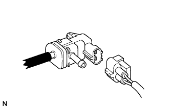 |
Disconnect the vacuum hose (on the canister side) of the purge VSV.
Start the engine.
Idle the engine.
Disconnect the connector of the purge VSV.
Check if air flows through the purge VSV.
Connect the connector of the purge VSV.
Connect the vacuum hose of the purge VSV.
|
| ||||
| OK | |
|
| 106.CHECK FUEL INJECTOR |
Clean the inside of the surge tank with compressed air.
After stopping the engine, measure the HC concentration inside the surge tank for 15 minutes.
| Result | Proceed to |
| 4000 ppm or higher | A |
| Less than 4000 ppm | B |
|
| ||||
| A | ||
| ||
| ||
| 107.CHECK INTAKE VALVE |
Check if carbon is on the intake valves.
| Result | Proceed to |
| Carbon present | A |
| No carbon present | B |
|
| ||||
| A | ||
| ||
| ||
| 108.READ VALUE USING TECHSTREAM (ISC LEARNING VALUE) |
Connect the Techstream to the DLC3.
Turn the ignition switch to ON.
Start the engine, turn off all accessory switches and warm up the engine until the engine coolant temperature stabilizes.
Using the Techstream, select and read [ISC Learning Value] in the Data List.
| Data List Item | Result | Suspected Area | Proceed to |
| ISC Learning Value | (engine displacement (liters) x 0.9) or more |
| A |
| Less than (engine displacement (liters) x 0.9) | - | B |
|
| ||||
| A | |
|
| 109.CHECK CYLINDER COMPRESSION PRESSURE |
Inspect the compression .
|
| ||||
| OK | ||
| ||
| ||
| 110.INSPECT ENGINE COOLANT TEMPERATURE SENSOR |
Inspect the engine coolant temperature sensor .
|
| ||||
| OK | |
|
| 111.CHECK CRANKSHAFT POSITION SENSOR |
Check the tightening and installation condition of the crankshaft position sensor bolt.
Check the connection of the crankshaft position sensor connector.
|
| ||||
| OK | |
|
| 112.CHECK CAMSHAFT POSITION SENSOR |
Check the tightening and installation condition of the camshaft position sensor bolt.
Check the connection of the camshaft position sensor connector.
|
| ||||
| OK | |
|
| 113.CHECK HARNESS AND CONNECTOR (CRANKSHAFT POSITION SENSOR - ECM) |
|
Disconnect the crankshaft position sensor connector.
Disconnect the ECM connector.
Measure the resistance according to the value(s) in the table below.
| Tester Connection | Condition | Specified Condition |
| D3-1 (NE+) - D74-110 (NE+) | Always | Below 1 Ω |
| D3-2 (NE-) - D74-111 (NE-) | Always | Below 1 Ω |
| D3-3 (VC) - D74-66 (VCV2) | Always | Below 1 Ω |
| D3-1 (NE+) or D74-110 (NE+) - Body ground | Always | 10 kΩ or higher |
| D3-2 (NE-) or D74-111 (NE-) - Body ground | Always | 10 kΩ or higher |
| D3-3 (VC) or D74-66 (VCV2) - Body ground | Always | 10 kΩ or higher |
|
| ||||
| OK | |
|
| 114.CHECK HARNESS AND CONNECTOR (CAMSHAFT POSITION SENSOR - ECM) |
|
Disconnect the camshaft position sensor connector.
Disconnect the ECM connector.
Measure the resistance according to the value(s) in the table below.
| Tester Connection | Condition | Specified Condition |
| D6-1 (G2) - D74-90 (G2) | Always | Below 1 Ω |
| D6-2 (G-) - D74-89 (G2-) | Always | Below 1 Ω |
| D6-3 (VC) - D74-66 (VCV2) | Always | Below 1 Ω |
| D6-1 (G2) or D74-90 (G2) - Body ground | Always | 10 kΩ or higher |
| D6-2 (G-) or D74-89 (G2-) - Body ground | Always | 10 kΩ or higher |
| D6-3 (VC) or D74-66 (VCV2) - Body ground | Always | 10 kΩ or higher |
|
| ||||
| OK | |
|
| 115.CHECK CRANKSHAFT POSITION SENSOR |
Replace the crankshaft position sensor (Click here).
Check the engine start operation.
|
| ||||
| OK | ||
| ||
| ||
| 116.CHECK CAMSHAFT POSITION SENSOR |
Replace the camshaft position sensor (Click here).
Check the engine start operation.
|
| ||||
| OK | ||
| ||
| ||

