WF1AM TRANSFER TRANSFER ASSEMBLY DISASSEMBLY
PROCEDURE

 36179
1.REMOVE LOWER TRANSFER CASE PROTECTOR
Remove the 4 bolts and lower transfer case protector.
82715D
2.REMOVE WIRING HARNESS CLAMP BRACKET
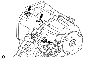
Remove the 3 bolts and 3 wiring harness clamp brackets.
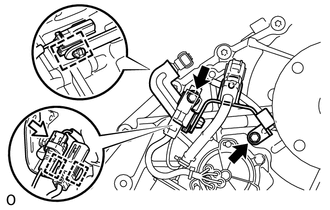
Disconnect the connector and 3 clamps.
Remove the 2 bolts and wiring harness clamp bracket.
36410J
3.REMOVE TRANSFER SHIFT ACTUATOR ASSEMBLY
33309C
4.REMOVE OUTPUT SHAFT COMPANION FLANGE SUB-ASSEMBLY (REAR)
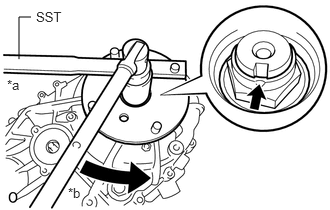
Using a chisel and hammer, loosen the staked part of the transfer output shaft nut.
- NOTICE:
- ·
Completely loosen the staked part of the transfer output shaft nut when removing it.
·Do not damage the threads of the rear transfer output shaft.
Using SST, hold the output shaft companion flange sub-assembly (rear).
- SST
- 09330-00021
| *a | Hold |
| *b | Turn |
Using a 30 mm socket wrench, remove the transfer output shaft nut.
Remove the O-ring.
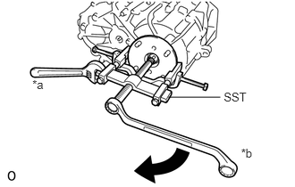
Using SST, remove the output shaft companion flange sub-assembly (rear).
- SST
- 09950-40011 (09951-04020, 09952-04010, 09953-04030, 09954-04010, 09955-04031, 09957-04010, 09958-04011)
| *a | Hold |
| *b | Turn |
36104A
5.REMOVE TRANSFER OUTPUT SHAFT TYPE T OIL SEAL
84222F
6.REMOVE TRANSFER INDICATOR SWITCH
36112
7.REMOVE REAR TRANSFER CASE
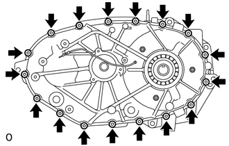
Using a 40 IP ''TORX PLUS'' socket wrench or T40 ''TORX'' socket wrench, remove the 17 bolts.
Remove the rear transfer case.
- HINT:
-
If necessary, tap the rear transfer case with a plastic-faced hammer to remove it.
44109C
8.REMOVE SOLENOID COIL SUB-ASSEMBLY
Disconnect the solenoid coil sub-assembly terminal.
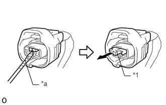
Remove the retainer from the coupler as shown in the illustration.
| *1 | Retainer |
| *a | Protective Tape |
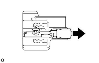
Detach the claw and disconnect the solenoid coil sub-assembly terminal.
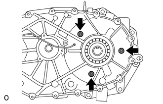
Remove the 3 nuts and solenoid coil sub-assembly.
- NOTICE:
-
Be careful not to drop the solenoid coil sub-assembly.
36102J
9.REMOVE TRANSFER COVER TYPE T OIL SEAL
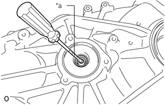
Using a screwdriver, remove the transfer cover type T oil seal.
| *a | Protective Tape |
- NOTICE:
-
Do not damage the rear transfer case.
- HINT:
-
Tape the screwdriver tip before use.
36292A
10.REMOVE TRANSFER DRIVEN SPROCKET BEARING (REAR)
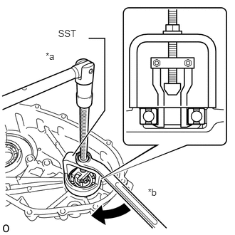
Using SST, remove the transfer driven sprocket bearing (rear).
- SST
- 09612-65014 (09612-01040)
| *a | Hold |
| *b | Turn |
36231J
11.REMOVE REAR TRANSFER OUTPUT SHAFT RADIAL BALL BEARING
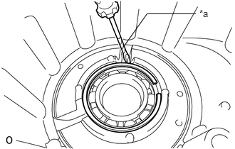
Using a screwdriver, remove the transfer output shaft rear shaft snap ring.
| *a | Protective Tape |
- HINT:
-
Tape the screwdriver tip before use.
Remove the rear transfer output shaft radial ball bearing.
44186
12.REMOVE SOLENOID COVER
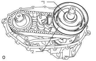
Remove the No. 1 transfer output shaft spacer and solenoid cover.
| *1 | No. 1 Transfer Output Shaft Spacer |
| *2 | Solenoid Cover |
36349
13.REMOVE TRANSFER SELECT RETURN SPRING
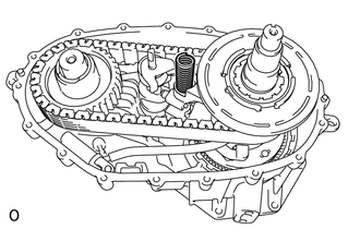
Remove the transfer select return spring.
36314
14.REMOVE TRANSFER HIGH AND LOW SHIFT FORK SHAFT
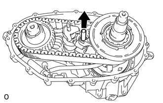
Remove the transfer high and low shift fork shaft.
35285B
15.REMOVE SOLENOID LOCK PLATE WITH NO. 2 TRANSFER GEAR SHIFT FORK
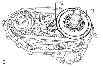
Remove the solenoid lock plate together with the No. 2 transfer gear shift fork.
| *1 | Solenoid Lock Plate |
| *2 | No. 2 Transfer Gear Shift Fork |
Remove the No. 2 transfer gear shift fork from the solenoid lock plate.
33806
16.REMOVE CONTROL SELECT SHAFT SUB-ASSEMBLY
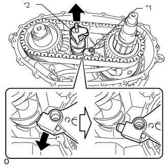
Remove the No. 1 transfer gear shift fork from the side of the control select shaft sub-assembly as shown in the illustration. Then remove the control select shaft sub-assembly.
| *1 | No. 1 Transfer Gear Shift Fork |
| *2 | Control Select Shaft Sub-assembly |
36205
17.REMOVE TRANSFER DRIVE SPROCKET SUB-ASSEMBLY
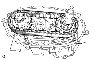
Remove the transfer drive sprocket sub-assembly together with the front transfer drive chain and transfer driven sprocket.
| *1 | Transfer Drive Sprocket Sub-assembly |
| *2 | Front Transfer Drive Chain |
| *3 | Transfer Driven Sprocket |
- NOTICE:
-
Do not drop the transfer drive sprocket sub-assembly, front transfer drive chain and transfer driven sprocket.
Remove the transfer drive sprocket sub-assembly and transfer driven sprocket from the front transfer drive chain.
36106K
18.REMOVE TRANSFER OIL PUMP BODY SUB-ASSEMBLY
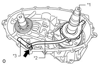
Using a T25 ''TORX'' socket wrench, remove the bolt and the transfer oil pump body sub-assembly together with the transfer oil tube and transfer oil strainer sub-assembly.
| *1 | Transfer Oil Pump Body Sub-assembly |
| *2 | Transfer Oil Tube |
| *3 | Transfer Oil Strainer Sub-assembly |
- HINT:
-
The sleeve does not have to be removed.
-
The transfer oil strainer sub-assembly comes with the sleeve installed.
Remove the transfer oil tube from the transfer oil pump body sub-assembly.
Remove the transfer oil strainer sub-assembly from the transfer oil tube.
33449D
19.REMOVE TRANSFER CASE MAGNET
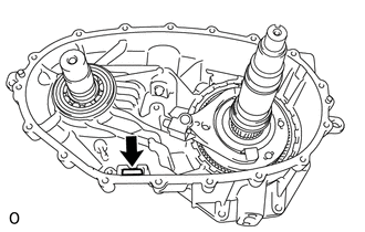
Remove the transfer case magnet.
36311F
20.REMOVE NO. 1 TRANSFER GEAR SHIFT FORK
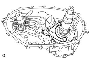
Remove the No. 1 transfer gear shift fork.
Inspect the gear shift fork pad (See page Drivetrain>WF1AM TRANSFER>TRANSFER ASSEMBLY>INSPECTION).
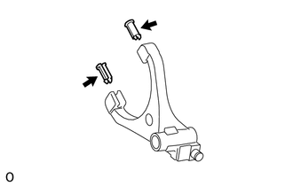
Remove the 2 gear shift fork pads from the No. 1 transfer gear shift fork.
- HINT:
-
It is not necessary to remove the 2 gear shift fork pads unless they are being replaced.
36231
21.REMOVE REAR TRANSFER OUTPUT SHAFT
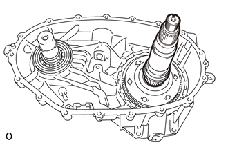
Remove the rear transfer output shaft.
36235
22.REMOVE TRANSFER HIGH AND LOW CLUTCH SLEEVE
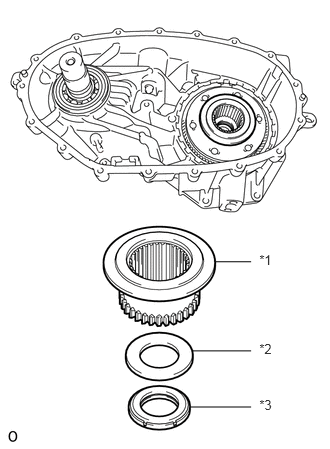
Remove the transfer high and low clutch sleeve, No. 2 transfer output shaft spacer and transfer lower planetary gear bearing.
| *1 | Transfer High and Low Clutch Sleeve |
| *2 | No. 2 Transfer Output Shaft Spacer |
| *3 | Transfer Lower Planetary Gear Bearing |
36270
23.REMOVE TRANSFER LOWER PLANETARY GEAR ASSEMBLY
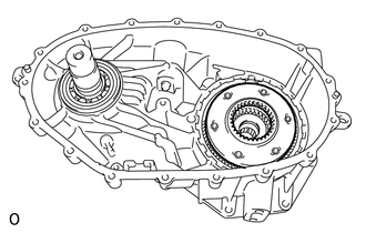
Remove the transfer lower planetary gear assembly.
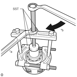
Using SST, remove the transfer input gear radial ball bearing.
- SST
- 09950-00020
09950-00030
09950-60010 (09951-00480)
| *a | Hold |
| *b | Turn |
36273
24.REMOVE TRANSFER LOWER PLANETARY RING GEAR
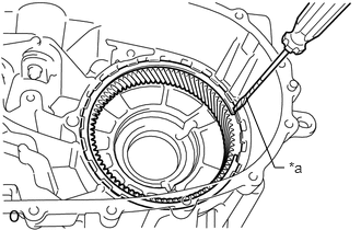
Using a screwdriver, remove the transfer lower planetary ring gear hole snap ring.
| *a | Protective Tape |
- HINT:
-
Tape the screwdriver tip before use.
Remove the transfer lower planetary ring gear.
25.REMOVE TRANSFER OIL SEPARATOR
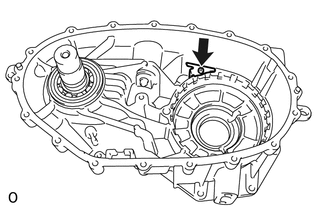
Using a T25 ''TORX'' socket wrench, remove the bolt and transfer oil separator.
33309B
26.REMOVE OUTPUT SHAFT COMPANION FLANGE SUB-ASSEMBLY (FRONT)
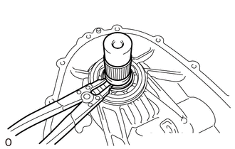
Using a snap ring expander, remove the shaft snap ring and output shaft companion flange sub-assembly (front).
- NOTICE:
-
Do not drop the output shaft companion flange sub-assembly (front).
36111X
27.REMOVE NO. 2 TRANSFER CASE OIL SEAL
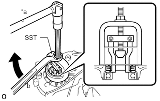
Using SST, remove the No. 2 transfer case oil seal.
- SST
- 09612-65014 (09612-01020)
| *a | Hold |
| *b | Turn |
36292A
28.REMOVE TRANSFER DRIVEN SPROCKET BEARING (FRONT)
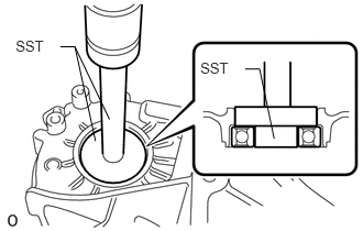
Using SST and a press, press out the transfer driven sprocket bearing (front).
- SST
- 09950-60010 (09951-00390, 09952-06010)
09950-60020 (09951-00730)
09950-70010 (09951-07100)
36111B
29.REMOVE TRANSFER CASE OIL SEAL
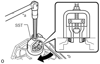
Using SST, remove the transfer case oil seal.
- SST
- 09612-65014 (09612-01020)
| *a | Hold |
| *b | Turn |