Home › Brake › BRAKE CONTROL / DYNAMIC CONTROL SYSTEMS › VEHICLE STABILITY CONTROL SYSTEM
RM27M0U _54 Brake _049153 BRAKE CONTROL / DYNAMIC CONTROL SYSTEMS _0234401 VEHICLE STABILITY CONTROL SYSTEM C

BRAKE CONTROL / DYNAMIC CONTROL SYSTEMS  VEHICLE STABILITY CONTROL SYSTEM  C1310/11  Open or Short in Active Brake Booster Circuit  


DESCRIPTION

Operates when booster's negative pressure is insufficient and allows for a stable braking control.

DTC Code DTC Detection Condition Trouble Area
C1310/11 Open or short in active brake booster solenoid circuit.
·

Brake booster

·

Active brake booster solenoid circuit


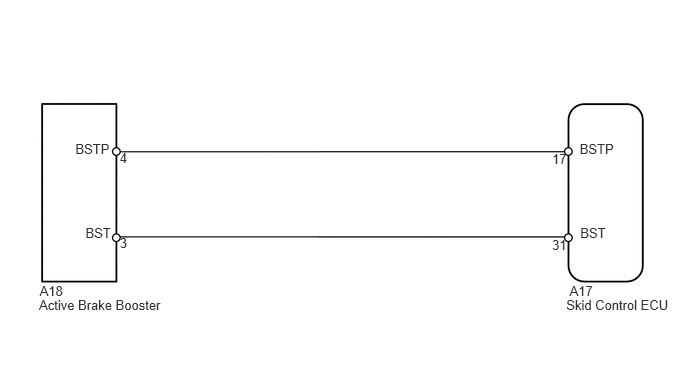
WIRING DIAGRAM

C152739E05
1.247,1.564 1.354,1.733 0.107,0.170 10 4 1.247,2.453 1.354,2.623 0.107,0.170 10 3 0.89,2.348 1.233,2.504 0.343,0.156 10 BST 0.785,1.472 1.232,1.628 0.448,0.156 10 BSTP 6.044,2.348 6.388,2.504 0.343,0.156 10 BST 6.038,1.472 6.486,1.628 0.448,0.156 10 BSTP 0.413,2.951 0.687,3.113 0.274,0.163 10 A18 0.406,3.091 1.784,3.281 1.378,0.191 10 Active Brake Booster 5.933,2.944 6.207,3.120 0.274,0.177 10 A17 5.898,3.091 7.040,3.267 1.142,0.177 10 Skid Control ECU 5.751,2.467 5.942,2.630 0.191,0.163 10 31 5.751,1.571 5.942,1.733 0.191,0.163 10 17

CAUTION / NOTICE / HINT

NOTICE:

When replacing the VSC actuator assembly, perform the zero point calibration (See page Brake>BRAKE CONTROL / DYNAMIC CONTROL SYSTEMS>VEHICLE STABILITY CONTROL SYSTEM>CALIBRATION).


HINT:

When the brake warning light illuminates, inspect and repair the trouble areas of the brake booster vacuum line first.


PROCEDURE
1.CHECK BRAKE BOOSTER ASSEMBLY
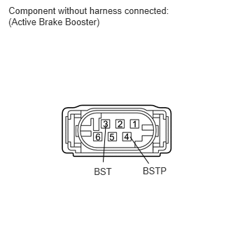
a.
C152740E03
0.126,0.07 2.643,0.420 2.517,0.350 10 Component without harness connected: (Active Brake Booster) 1.398,2.468 1.710,2.630 0.312,0.163 10 BST 2.124,2.463 2.523,2.643 0.399,0.180 10 BSTP 1.935,2.034 2.214,2.433 false 1.574,1.853 1.535,2.412 false

Disconnect the A18 booster connector.


b.

Measure the resistance according to the value(s) in the table below.

Standard Resistance:
Tester Connection Condition Specified Condition
3 (BST) - 4 (BSTP) Always 1.1 to 1.7 Ω


OK

2.CHECK HARNESS AND CONNECTOR (SKID CONTROL ECU - ACTIVE BRAKE BOOSTER)

NG

REPLACE BRAKE BOOSTER ASSEMBLY

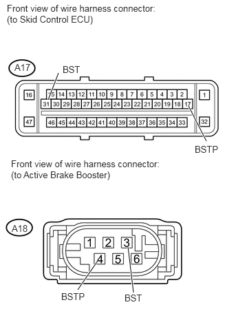
2.CHECK HARNESS AND CONNECTOR (SKID CONTROL ECU - ACTIVE BRAKE BOOSTER)
a.
U152488E02
0.885,1.104 0.729,1.51 true 3.125,2.135 2.854,1.604 true 1.479,3.948 1.177,4.385 true 1.938,3.74 2.021,4.427 true 0.219,0.938 0.5,1.104 0.281,0.167 10 false A17 0.177,3.375 0.458,3.542 0.281,0.167 10 false A18 0.948,0.969 1.26,1.135 0.313,0.167 10 false BST 1.885,4.427 2.198,4.594 0.313,0.167 10 false BST 2.948,2.177 3.365,2.344 0.417,0.167 10 false BSTP 0.927,4.406 1.344,4.573 0.417,0.167 10 false BSTP 0.104,0.042 2.385,0.375 2.281,0.333 10 false Front view of wire harness connector: (to Skid Control ECU) 0.167,2.396 2.458,2.76 2.292,0.365 10 false Front view of wire harness connector: (to Active Brake Booster)

Confirm that the skid control ECU connector and active brake booster connector are properly connected.


b.

Disconnect the A17 ECU connector.


c.

Disconnect the A18 booster connector.


d.

Inspect both the connector case and the terminal for deformation and corrosion.

OK:

No deformation or corrosion.


e.

Measure the resistance according to the value(s) in the table below.

Standard Resistance:
Tester Connection Condition Specified Condition
A17-31 (BST) - A18-3 (BST) Always Below 1 Ω
A17-31 (BST) - Body ground Always 10 kΩ or higher
A17-17 (BSTP) - A18-4 (BSTP) Always Below 1 Ω
A17-17 (BSTP) - Body ground Always 10 kΩ or higher


OK

NG

REPAIR OR REPLACE HARNESS OR CONNECTOR