BRAKE CONTROL / DYNAMIC CONTROL SYSTEMS VEHICLE STABILITY CONTROL SYSTEM C1311/12 Open or Short in Brake Inhibit Relay Circuit C1380/64 Stop Light Control Relay Malfunction
DESCRIPTION
The stop light control relays are built into the stop light circuit and prohibits the stop light from turning on under VSC control.
| DTC Code | DTC Detection Condition | Trouble Area |
|---|---|---|
| C1311/12 | Open or short circuit is detected. | ·
Stop light control relay ·
Stop light control circuit |
| C1380/64 | Open or short circuit is detected. | ·
Stop light control relay ·
Stop light control circuit |
WIRING DIAGRAM
Refer to DTC C1249/49 (See page Brake>BRAKE CONTROL / DYNAMIC CONTROL SYSTEMS>VEHICLE STABILITY CONTROL SYSTEM>C1249/49).
CAUTION / NOTICE / HINT
- NOTICE:
-
When replacing the VSC actuator assembly, perform the zero point calibration (See page Brake>BRAKE CONTROL / DYNAMIC CONTROL SYSTEMS>VEHICLE STABILITY CONTROL SYSTEM>CALIBRATION).
PROCEDURE
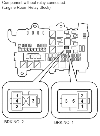
Remove the stop light control relays from the engine room relay block.
Measure the voltage according to the value(s) in the table below.
- Standard Voltage:
Tester Connection Switch Condition Specified Condition Stop light control relay terminal 1 (BRK NO. 1) - Body ground Ignition switch ON 11 to 14 V Stop light control relay terminal 1 (BRK NO. 2) - Body ground
OK
NG
Remove the stop light control relays (BRK NO. 1 and BRK NO. 2) from the engine room relay block.
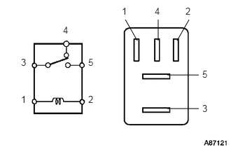
Measure the resistance according to the value(s) in the table below.
- Standard Resistance:
- for BRK NO. 1:
Tester Connection Condition Specified Condition 3 - 4 When battery voltage is not applied to terminals 1 and 2 Below 1 Ω 3 - 5 When battery voltage is not applied to terminals 1 and 2 10 kΩ or higher 3 - 4 When battery voltage is applied to terminals 1 and 2 10 kΩ or higher 3 - 5 When battery voltage is applied to terminals 1 and 2 Below 1 Ω
- for BRK NO. 2:
Tester Connection Condition Specified Condition 3 - 4 When battery voltage is not applied to terminals 1 and 2 Below 1 Ω When battery voltage is applied to terminals 1 and 2 10 kΩ or higher
OK
NG
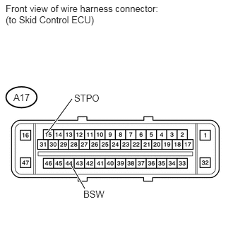
Disconnect the A17 ECU connector.
Measure the voltage according to the value(s) in the table below.
- Standard Voltage:
Tester Connection Switch Condition Specified Condition A17-44 (BSW) - Body ground Ignition switch ON 11 to 14 V A17-15 (STPO) - Body ground Ignition switch ON 11 to 14 V
OK
NG