Home › Brake › BRAKE CONTROL / DYNAMIC CONTROL SYSTEMS › VEHICLE STABILITY CONTROL SYSTEM
RM27M0U _54 Brake _049153 BRAKE CONTROL / DYNAMIC CONTROL SYSTEMS _0234401 VEHICLE STABILITY CONTROL SYSTEM C

BRAKE CONTROL / DYNAMIC CONTROL SYSTEMS  VEHICLE STABILITY CONTROL SYSTEM  C1267/28  Brake Pedal Load Sensing Switch  


DESCRIPTION

The skid control ECU detects if the brake pedal is depressed.

DTC No. DTC Detection Condition Trouble Area
C1267/28 When one of following conditions is met:
1.

Micro switch signal PSNC and PSNO logic malfunction.

2.

When brake pedal is not depressed, micro switch turns on.

3.

When brake pedal is depressed, micro switch turns off.


·

Booster pedal micro switch (Active brake booster)

·

Booster pedal micro switch (Active brake booster) circuit


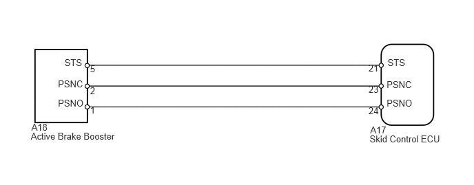
WIRING DIAGRAM

C152731E11
0.475,1.843 0.779,2.026 0.304,0.184 10 A18 0.466,1.983 2.038,2.178 1.573,0.195 10 Active Brake Booster 5.598,1.885 5.902,2.068 0.304,0.184 10 A17 5.589,2.025 6.800,2.227 1.211,0.202 10 Skid Control ECU 0.975,0.867 1.316,1.041 0.341,0.174 10 STS 0.877,1.184 1.315,1.359 0.438,0.174 10 PSNC 0.877,1.478 1.315,1.653 0.438,0.174 10 PSNO 5.86,0.867 6.201,1.041 0.341,0.174 10 STS 5.846,1.478 6.284,1.653 0.438,0.174 10 PSNO 5.846,1.198 6.284,1.373 0.438,0.174 10 PSNC 1.362,0.958 1.490,1.127 0.128,0.170 10 5 1.362,1.294 1.490,1.464 0.128,0.170 10 2 1.362,1.588 1.490,1.758 0.128,0.170 10 1 5.572,0.951 5.763,1.120 0.191,0.170 10 21 5.572,1.273 5.763,1.443 0.191,0.170 10 23 5.572,1.59 5.763,1.760 0.191,0.170 10 24

CAUTION / NOTICE / HINT

NOTICE:

When replacing the VSC actuator assembly, perform zero point calibration (See page Brake>BRAKE CONTROL / DYNAMIC CONTROL SYSTEMS>VEHICLE STABILITY CONTROL SYSTEM>CALIBRATION).


PROCEDURE
1.CHECK TERMINAL VOLTAGE (BOOSTER PEDAL MICRO SWITCH)
a.
U152335E01
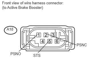
0.075,0.024 2.488,0.354 2.413,0.330 10 Front view of wire harness connector: (to Active Brake Booster) 0.243,0.975 0.572,1.151 0.330,0.177 10 A18 1.371,1.939 1.687,2.116 0.316,0.177 10 STS 1.779,1.512 1.539,1.93 false

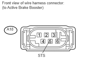
Disconnect A18 booster connector.


b.

Turn the ignition switch to ON.


c.

Measure the voltage according to the value(s) in the table below.

Standard Voltage:
Tester Connection Switch Condition Specified Condition
A18-5 (STS) - Body ground Ignition switch ON 4.3 to 6.3 V


OK

2.CHECK BOOSTER PEDAL MICRO SWITCH

NG

3.CHECK HARNESS AND CONNECTOR (BOOSTER PEDAL MICRO SWITCH - SKID CONTROL ECU)
2.CHECK BOOSTER PEDAL MICRO SWITCH
C162424E05
0.244,0.715 0.485,0.885 0.241,0.170 10 ON 2.337,0.576 3.240,0.746 0.903,0.170 10 (Oscilloscope) 2.337,2.173 3.240,2.343 0.903,0.170 10 (Oscilloscope) 0.291,1.663 0.909,1.814 0.618,0.151 10 2 (PSNC) 0.245,1.101 0.932,1.253 0.687,0.151 10 1 (PSNO) 1.399,1.358 0.897,1.168 false 1.399,1.473 0.909,1.735 false 1.927,1.222 2.444,1.373 0.517,0.151 10 5 (STS) 1.504,1.522 1.915,1.296 false 3.511,0.071 4.279,0.241 0.767,0.170 10 (Reference) 4.366,0.509 5.226,0.832 0.860,0.323 10 Brake pedal released 5.645,0.509 6.453,0.834 0.808,0.325 10 Brake pedal depressed 5.953,1.234 6.697,1.404 0.744,0.170 10 PSNO-STS 5.953,1.682 6.697,1.852 0.744,0.170 10 PSNC-STS 5.917,1.305 5.763,1.121 false 5.917,1.744 5.763,2.027 false 3.768,1.04 4.161,1.210 0.393,0.170 10 6.7 V 3.768,1.334 4.022,1.504 0.254,0.170 10 0 V 3.768,1.656 4.161,1.826 0.393,0.170 10 6.7 V 3.768,1.95 4.022,2.120 0.254,0.170 10 0 V 4.366,0.25 5.560,0.428 1.194,0.178 10 Ignition switch ON

a.

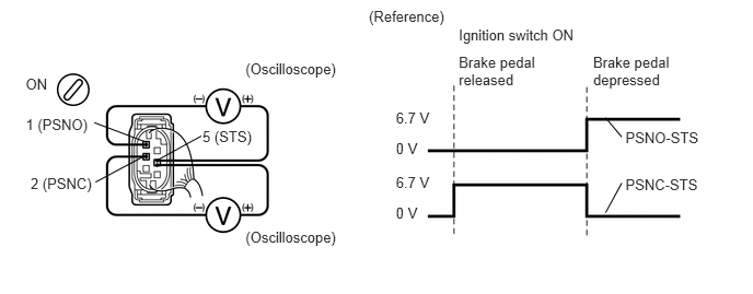
When using an oscilloscope:

i.

Connect the oscilloscope between terminals 1 (PSNO) and 5 (STS), 2 (PSNC) and 5 (STS) of the brake booster with connector being connected.


ii.

Turn the ignition switch to ON.


iii.

Check the signal waveform while the brake pedal is depressed and released.

OK:

Signal waveform changes as shown in the illustration.


b.
U152334E01
1.37,1.258 0.691,1.871 false 0.075,0.024 2.488,0.423 2.413,0.399 10 Front view of wire harness connector: (to Active Brake Booster) 0.243,0.975 0.572,1.151 0.330,0.177 10 A18 0.381,1.879 0.801,2.055 0.420,0.177 10 PSNO 2.802,1.555 3.222,1.732 0.420,0.177 10 PSNC 1.216,1.939 1.532,2.116 0.316,0.177 10 STS 1.735,1.246 2.785,1.635 false 1.771,1.512 1.384,1.93 false

When not using an oscilloscope:

i.

Disconnect the A18 booster connector.


ii.

Turn the ignition switch to ON.


iii.

Measure the voltage according to the value(s) in the table below.

Standard Voltage:
Tester Connection Condition Specified Condition
A18-2 (PSNC) - A18-5 (STS) Brake pedal is depressed 6 V
A18-1 (PSNO) - A18-5 (STS) Brake pedal is released


OK

3.CHECK HARNESS AND CONNECTOR (BOOSTER PEDAL MICRO SWITCH - SKID CONTROL ECU)

NG

REPLACE BRAKE BOOSTER ASSEMBLY

3.CHECK HARNESS AND CONNECTOR (BOOSTER PEDAL MICRO SWITCH - SKID CONTROL ECU)
a.
U152489E02
2.052,1.125 1.927,1.542 true 2.615,1.115 2.219,1.521 true 1.76,1.552 1.49,1.115 true 1.625,3.719 1.333,4.396 true 1.781,3.958 1.979,4.417 true 1.333,3.708 0.573,4.323 true 0.219,0.948 0.5,1.115 0.281,0.167 10 false A17 0.167,3.354 0.448,3.521 0.281,0.167 10 false A18 1.927,0.906 2.354,1.073 0.427,0.167 10 false PSNC 1.26,0.885 1.677,1.052 0.417,0.167 10 false PSNO 2.646,0.958 2.958,1.125 0.313,0.167 10 false STS 1.073,4.427 1.5,4.594 0.427,0.167 10 false PSNC 0.302,4.385 0.719,4.552 0.417,0.167 10 false PSNO 1.927,4.448 2.24,4.615 0.313,0.167 10 false STS 0.042,0.01 2.333,0.333 2.292,0.323 10 false Front view of wire harness connector: (to Skid Control ECU) 0.042,2.417 2.313,2.75 2.271,0.333 10 false Front view of wire harness connector: (to Active Brake Booster)

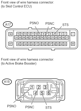
Confirm that the skid control ECU connector and brake booster connector are properly connected.


b.

Disconnect the A17 ECU connector.


c.

Disconnect the A18 booster connector.


d.

Inspect both the connector case and the terminal for deformation and corrosion.

OK:

No deformation or corrosion.


e.

Measure the resistance according to the value(s) in the table below.

Standard Resistance:
Tester Connection Condition Specified Condition
A17-23 (PSNC) - A18-2 (PSNC) Always Below 1 Ω
A17-23 (PSNC) - Body ground Always 10 kΩ or higher
A17-24 (PSNO) - A18-1 (PSNO) Always Below 1 Ω
A17-24 (PSNO) - Body ground Always 10 kΩ or higher
A17-21 (STS) - A18-5 (STS) Always Below 1 Ω
A17-21 (STS) - Body ground Always 10 kΩ or higher


OK

NG

REPAIR OR REPLACE HARNESS OR CONNECTOR