Home › Vehicle Interior › ENGINE IMMOBILISER › ENGINE IMMOBILISER SYSTEM
RM27M0U _58 Vehicle Interior _049156 ENGINE IMMOBILISER _0234432 ENGINE IMMOBILISER SYSTEM J

ENGINE IMMOBILISER  ENGINE IMMOBILISER SYSTEM  Security Indicator Light Circuit  


DESCRIPTION

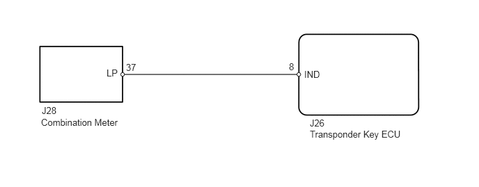
When a key is registered, the transponder key ECU outputs the key registration condition by lighting up, blinking or turning OFF the security indicator light.

WIRING DIAGRAM
B443050E01
1.594,1.01 1.906,1.208 0.313,0.198 10 false LP 1.885,0.927 2.198,1.125 0.313,0.198 10 false 37 4.323,0.917 4.479,1.115 0.156,0.198 10 false 8 4.552,1.031 5.01,1.229 0.458,0.198 10 false IND 0.625,1.573 1.083,1.771 0.458,0.198 10 false J28 0.615,1.75 1.813,1.938 1.198,0.188 10 false Combination Meter 4.635,1.76 5.094,1.958 0.458,0.198 10 false J26 4.635,1.927 5.99,2.156 1.354,0.229 10 false Transponder Key ECU

CAUTION / NOTICE / HINT

HINT:

When the transponder key ECU is replaced, reregister the ECU - ECM communication ID (see page Vehicle Interior>ENGINE IMMOBILISER>ENGINE IMMOBILISER SYSTEM>REGISTRATION).


PROCEDURE

1.PERFORM ACTIVE TEST USING TECHSTREAM (SECURITY INDICATOR LIGHT)
a.

Select the Active Test and use the Techstream to generate a command.


b.

Check that the security indicator light operation is normal.

Immobiliser
Tester Display Test Part Control Range Diagnostic Note
Security Indicator Security indicator light ON/OFF -

OK:

Security indicator light turns ON and OFF.


OK

2.CHECK TRANSPONDER KEY ECU

NG

3.CHECK HARNESS AND CONNECTOR (SECURITY INDICATOR LIGHT - TRANSPONDER KEY ECU)
2.CHECK TRANSPONDER KEY ECU
a.
U151860E01
1.899,2.729 2.155,2.875 0.257,0.147 10 IND 2.015,2.113 2.023,2.729 false 0.089,0.199 2.482,0.541 2.393,0.342 10 Component with harness connected: (Transponder Key ECU) 1.546,1.118 1.864,1.300 0.318,0.183 10 J26

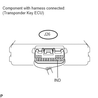
Remove the transponder key ECU with the connector still connected (see page Vehicle Interior>ENGINE IMMOBILISER>TRANSPONDER KEY ECU>REMOVAL).


b.

Measure the voltage according to the value(s) in the table below.

Standard voltage:
Tester Connection Condition Specified Condition
J26-8 (IND) - Body ground Engine immobiliser system is set Alternating between 11 to 14 V and below 1 V


OK

PROCEED TO NEXT CIRCUIT INSPECTION SHOWN IN PROBLEM SYMPTOMS TABLE

NG

3.CHECK HARNESS AND CONNECTOR (SECURITY INDICATOR LIGHT - TRANSPONDER KEY ECU)
a.

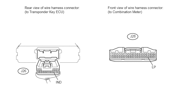
Disconnect the J28 combination meter connector.

U152069E02
2.177,2.938 2.344,3.24 false 5.979,2.313 6.188,2.656 false 1,0.229 3.354,0.688 2.354,0.458 10 false Rear view of wire harness connector: (to Transponder Key ECU) 4.365,0.229 6.698,0.677 2.333,0.448 10 false Front view of wire harness connector: (to Combination Meter) 2.26,3.25 2.563,3.427 0.302,0.177 10 false IND 6.146,2.635 6.448,2.813 0.302,0.177 10 false LP 0.844,2.792 1.135,2.99 0.292,0.198 10 false J26 5.271,1.385 5.563,1.583 0.292,0.198 10 false J28

b.

Disconnect the J26 transponder key ECU connector.


c.

Measure the resistance according to the value(s) in the table below.

Standard resistance:
Tester Connection Condition Specified Condition
J28-37 (LP) - J26-8 (IND) Always Below 1 Ω
J28-37 (LP) - Body ground Always 10 kΩ or higher


OK

4.REPLACE COMBINATION METER ASSEMBLY

NG

REPAIR OR REPLACE HARNESS OR CONNECTOR

4.REPLACE COMBINATION METER ASSEMBLY
a.

Temporarily replace the combination meter assembly with a new or normally functioning one (See page Vehicle Interior>METER / GAUGE / DISPLAY>COMBINATION METER>REMOVAL).


b.

Check security indicator light.

OK:

Security indicator illuminates.


OK

END (COMBINATION METER WAS DEFECTIVE)

NG

REPLACE MAIN BODY ECU