PARK ASSIST / MONITORING CLEARANCE WARNING ECU INSTALLATION
CAUTION / NOTICE / HINT
- HINT:
-
A bolt without a torque specification is shown in the standard bolt chart (See page General>SPECIFICATIONS>STANDARD BOLT>SPECIFIED TORQUE FOR STANDARD BOLTS).
PROCEDURE

 89340A
1.INSTALL CLEARANCE WARNING ECU ASSEMBLY
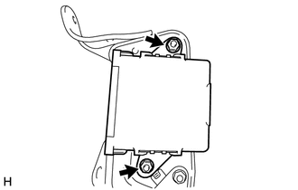
Install the clearance warning ECU assembly to the bracket with the 2 nuts.
- NOTICE:
- ·
Avoid any impact to the clearance warning ECU assembly.
·Do not drop the ECU. If it is dropped, replace it with a new one.
2.INSTALL CLEARANCE WARNING ECU WITH BRACKET
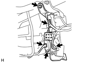
Install the clearance warning ECU with bracket with the nut and bolt.
Connect the ECU connectors and attach the harness clamp.
- NOTICE:
-
Do not apply excessive force to the wire harnesses.
55045A
3.INSTALL LOWER INSTRUMENT PANEL FINISH PANEL SUB-ASSEMBLY RH
55475A
4.INSTALL NO.2 INSTRUMENT CLUSTER FINISH PANEL GARNISH
55317A
5.INSTALL INSTRUMENT SIDE PANEL RH
55064A
6.INSTALL NO.4 INSTRUMENT REGISTER SUB-ASSEMBLY
73990
7.INSTALL LOWER NO. 2 INSTRUMENT PANEL AIRBAG ASSEMBLY
55312
8.INSTALL LOWER INSTRUMENT PANEL
55607
9.INSTALL NO. 2 INSTRUMENT PANEL UNDER COVER SUB-ASSEMBLY
10.CONNECT CABLE TO NEGATIVE BATTERY TERMINAL
- NOTICE:
-
When disconnecting the cable, some systems need to be initialized after the cable is reconnected (See page General>INTRODUCTION>REPAIR INSTRUCTION>INITIALIZATION).
11. CHECK SRS WARNING LIGHT
Check the SRS warning light (See page Vehicle Interior>SUPPLEMENTAL RESTRAINT SYSTEMS>DRIVER SIDE KNEE AIRBAG ASSEMBLY>INSTALLATION).