Home › Vehicle Interior › WINDOW / GLASS › POWER WINDOW CONTROL SYSTEM(w/o Jam Protection Function)
RM27M0U _58 Vehicle Interior _049161 WINDOW / GLASS _0234466 POWER WINDOW CONTROL SYSTEM(w/o Jam Protection Function) J

WINDOW / GLASS  POWER WINDOW CONTROL SYSTEM(w/o Jam Protection Function)  Rear Power Window LH does not Operate with Rear Power Window Switch LH  


DESCRIPTION

HINT:

for Double Cab, CrewMax


If the rear LH side manual UP/DOWN function does not operate, there may be a malfunction in the rear switch LH, rear motor LH, master switch or harness and connector.


WIRING DIAGRAM
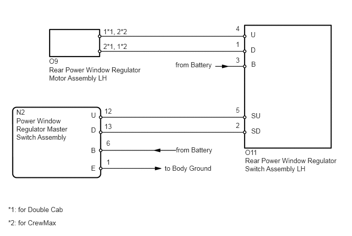
B173121E08
1.854,3.354 2.021,3.552 0.167,0.198 10 false E 1.854,2.99 2.021,3.188 0.167,0.198 10 false B 1.854,2.271 2.146,2.469 0.292,0.198 10 false U 4.802,1.146 4.927,1.333 0.125,0.188 10 false 3 4.802,2.167 5.094,2.365 0.292,0.198 10 false 5 4.802,2.479 5.094,2.677 0.292,0.198 10 false 2 2.104,0.563 2.635,0.729 0.531,0.167 10 false 1*1, 2*2 2.104,0.865 2.677,1.042 0.573,0.177 10 false 2*1, 1*2 3.573,1.24 4.375,1.448 0.802,0.208 10 false from Battery 3.354,3.354 4.344,3.542 0.99,0.188 10 false to Body Ground 1.854,2.573 2.146,2.771 0.292,0.198 10 false D 5.115,2.594 5.406,2.792 0.292,0.198 10 false SD 5.115,2.281 5.406,2.479 0.292,0.198 10 false SU 5.115,1.229 5.406,1.427 0.292,0.198 10 false B 3.583,2.979 4.365,3.177 0.781,0.198 10 true from Battery 4.802,0.5 4.938,0.688 0.135,0.188 10 false 4 4.802,0.823 4.927,1.021 0.125,0.198 10 false 1 2.125,2.188 2.458,2.385 0.333,0.198 10 false 12 2.125,2.5 2.469,2.698 0.344,0.198 10 false 13 2.167,2.844 2.375,3.042 0.208,0.198 10 false 6 2.167,3.229 2.458,3.427 0.292,0.198 10 false 1 0.333,2.208 0.604,2.396 0.271,0.188 10 false N2 0.333,2.385 1.5,2.927 1.167,0.542 10 false Power Window Regulator Master Switch Assembly 4.99,3.031 5.313,3.208 0.323,0.177 10 false O11 4.99,3.198 6.938,3.552 1.948,0.354 10 false Rear Power Window Regulator Switch Assembly LH 1,1.344 3.021,1.688 2.021,0.344 10 false Rear Power Window Regulator Motor Assembly LH 5.104,0.625 5.396,0.823 0.292,0.198 10 false U 5.104,0.938 5.396,1.135 0.292,0.198 10 false D 0.167,4.198 1.5,4.365 1.333,0.167 10 false *1: for Double Cab 0.167,4.469 1.208,4.635 1.042,0.167 10 false *2: for CrewMax 1,1.167 1.26,1.344 0.26,0.177 10 false O9

PROCEDURE

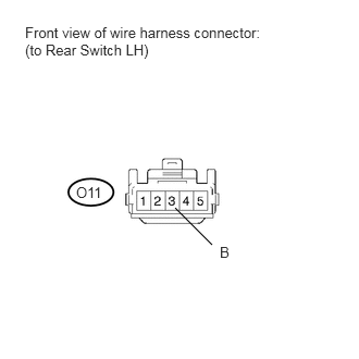
1.CHECK HARNESS AND CONNECTOR (REAR SWITCH LH - BATTERY)
U151868E02
1.677,1.99 2.031,2.344 false 0.24,0.229 2.531,0.635 2.292,0.406 10 false Front view of wire harness connector: (to Rear Switch LH) 0.729,1.76 1.021,1.906 0.292,0.146 10 false O11 2.104,2.333 2.25,2.5 0.146,0.167 10 false B

a.

Disconnect the O11 switch connector.


b.

Measure the voltage according to the value(s) in the table below.

Standard Voltage:
Tester Connection Switch Condition Specified Condition
O11-3 (B) - Body ground Ignition switch ON 11 to 14 V


OK

2.INSPECT REAR POWER WINDOW REGULATOR SWITCH ASSEMBLY LH

NG

REPAIR OR REPLACE HARNESS OR CONNECTOR

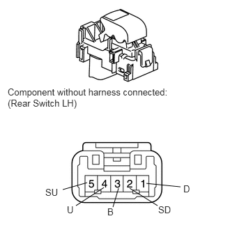
2.INSPECT REAR POWER WINDOW REGULATOR SWITCH ASSEMBLY LH
B166135E15
1.302,2.729 0.938,2.833 false 1.552,2.802 1.135,3.073 false 1.771,2.813 1.688,3.094 false 1.938,2.813 2.354,3.073 false 2.188,2.74 2.698,2.792 false 0.115,1.292 2.583,1.656 2.469,0.365 10 false Component without harness connected: (Rear Switch LH) 0.677,2.792 1,2.969 0.323,0.177 10 false SU 1,3.052 1.198,3.229 0.198,0.177 10 false U 1.604,3.083 1.781,3.26 0.177,0.177 10 false B 2.365,3.052 2.625,3.229 0.26,0.177 10 false SD 2.74,2.74 2.917,2.917 0.177,0.177 10 false D

a.

b.

Measure the resistance according to the value(s) in the table below.

Standard Resistance:
Tester Connection Switch Condition Specified Condition
4 (U) - 3 (B) UP Below 1 Ω
1 (D) - 2 (SD)
4 (U) - 5 (SU) OFF Below 1 Ω
1 (D) - 2 (SD)
4 (U) - 5 (SU) DOWN Below 1 Ω
1 (D) - 3 (B)


OK

3.CHECK HARNESS AND CONNECTOR (REAR SWITCH LH - REAR MOTOR LH)

NG

REPLACE REAR POWER WINDOW REGULATOR SWITCH ASSEMBLY LH

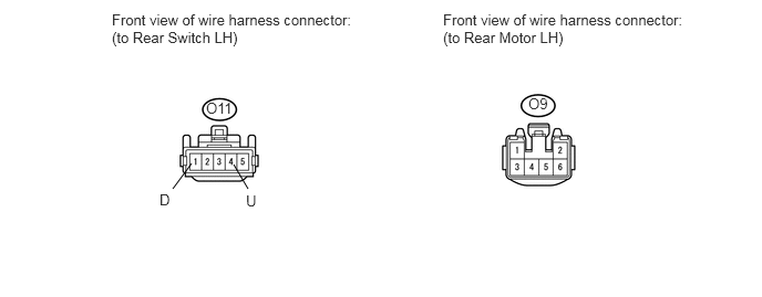
3.CHECK HARNESS AND CONNECTOR (REAR SWITCH LH - REAR MOTOR LH)
U151982E02
1.625,1.781 1.802,1.542 false 2.333,1.781 2.198,1.552 false 1.052,0.104 3.313,0.479 2.26,0.375 10 false Front view of wire harness connector: (to Rear Switch LH) 4.167,0.104 6.427,0.49 2.26,0.385 10 false Front view of wire harness connector: (to Rear Motor LH) 1.938,0.938 2.229,1.104 0.292,0.167 10 false O11 2.313,1.813 2.469,1.969 0.156,0.156 10 false U 1.5,1.802 1.635,1.99 0.135,0.188 10 false D 4.969,0.896 5.188,1.073 0.219,0.177 10 false O9

a.

Disconnect the O11 switch connector.


b.

Disconnect the O9 motor connector.


c.

Measure the resistance according to the value(s) in the table below.

Standard Resistance:
for Double Cab:
Tester Connection Condition Specified Condition
O11-1 (D) - O9-2 Always Below 1 Ω
O11-4 (U) - O9-1 Always Below 1 Ω
O11-1 (D) or O9-2 - Body ground Always 10 kΩ or higher
O11-4 (U) or O9-1 - Body ground Always 10 kΩ or higher

for CrewMax:
Tester Connection Condition Specified Condition
O11-1 (D) - O9-1 Always Below 1 Ω
O11-4 (U) - O9-2 Always Below 1 Ω
O11-1 (D) or O9-1 - Body ground Always 10 kΩ or higher
O11-4 (U) or O9-2 - Body ground Always 10 kΩ or higher


OK

4.INSPECT REAR POWER WINDOW REGULATOR MOTOR ASSEMBLY LH

NG

REPAIR OR REPLACE HARNESS OR CONNECTOR

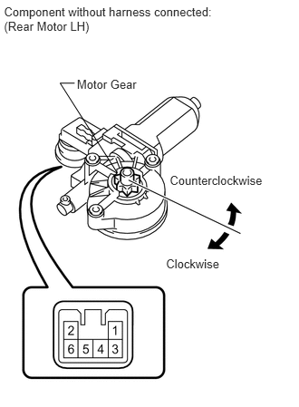
4.INSPECT REAR POWER WINDOW REGULATOR MOTOR ASSEMBLY LH
B231474E04
1.349,1.988 0.691,0.955 0.691,0.955 0.858,0.955 false 0.884,0.882 1.623,1.034 0.739,0.152 10 Motor Gear 1.909,2.952 2.589,3.098 0.680,0.145 10 Clockwise 1.952,1.993 3.073,2.138 1.121,0.145 10 Counterclockwise 0.046,0.05 2.707,0.494 2.661,0.445 10 Component without harness connected: (Rear Motor LH)


b.

Apply battery voltage to connector terminals 1 and 2.


c.

Check that the motor gear rotates smoothly as follows.

OK:
for Double Cab:
Measurement Condition Specified Condition
Battery positive (+) → 1
Battery negative (-) → 2
Motor gear rotates clockwise
Battery positive (+) → 2
Battery negative (-) → 1
Motor gear rotates counterclockwise

for CrewMax:
Measurement Condition Specified Condition
Battery positive (+) → 1
Battery negative (-) → 2
Motor gear rotates counterclockwise
Battery positive (+) → 2
Battery negative (-) → 1
Motor gear rotates clockwise


OK

5.CHECK HARNESS AND CONNECTOR (MASTER SWITCH - REAR SWITCH LH)

NG

REPLACE REAR POWER WINDOW REGULATOR MOTOR ASSEMBLY LH

5.CHECK HARNESS AND CONNECTOR (MASTER SWITCH - REAR SWITCH LH)
U151985E02
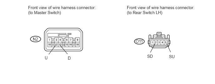
5.167,1.458 5.01,1.75 false 5.552,1.448 5.688,1.74 false 2,1.51 2.25,1.802 false 1.854,1.51 1.625,1.813 false 0.938,0.167 3.208,0.521 2.271,0.354 10 false Front view of wire harness connector: (to Master Switch) 1.094,1.219 1.302,1.385 0.208,0.167 10 false N2 4.906,1.792 5.135,1.979 0.229,0.188 10 false SD 5.635,1.802 5.896,1.99 0.26,0.188 10 false SU 4.229,0.167 6.521,0.552 2.292,0.385 10 false Front view of wire harness connector: (to Rear Switch LH) 1.49,1.844 1.625,2.042 0.135,0.198 10 false U 2.26,1.854 2.427,2.021 0.167,0.167 10 false D 4.521,1.292 4.802,1.458 0.281,0.167 10 false O11

a.

Disconnect the N2 master switch connector.


b.

Disconnect the O11 switch connector.


c.

Measure the resistance according to the value(s) in the table below.

Standard Resistance:
Tester Connection Condition Specified Condition
N2-12 (U) - O11-5 (SU) Always Below 1 Ω
N2-13 (D) - O11-2 (SD)
N2-12 (U) or O11-5 (SU) - Body ground Always 10 kΩ or higher
N2-13 (D) or O11-2 (SD) - Body ground


OK

6.CHECK POWER WINDOW REGULATOR MASTER SWITCH ASSEMBLY

NG

REPAIR OR REPLACE HARNESS OR CONNECTOR

6.CHECK POWER WINDOW REGULATOR MASTER SWITCH ASSEMBLY
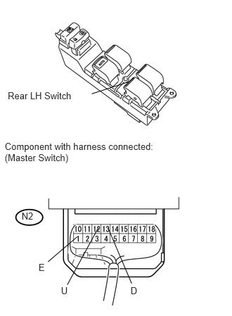
U151912E01
0.07,2.086 2.691,2.485 2.621,0.399 10 Component with harness connected: (Master Switch) 0.571,3.874 0.734,4.028 0.163,0.154 10 E 1.934,4.222 2.298,4.377 0.364,0.154 10 D 0.904,4.222 1.233,4.376 0.330,0.154 10 U 1.142,3.505 0.711,3.874 false 1.599,3.37 1.951,4.197 false 1.457,3.369 0.997,4.214 false 0.115,1.337 1.194,1.541 1.080,0.205 10 Rear LH Switch 1.36,1.388 1.901,1.213 false 0.319,3.117 0.566,3.273 0.246,0.156 10 N2


b.

Reconnect the master switch connector.


c.

Measure the voltage according to the value(s) in the table below.

Standard Voltage:
Tester Connection Switch Condition Specified Condition
N2-12 (U) - N2-1 (E) Ignition switch ON, rear LH switch of master switch OFF → UP Below 1 V → 11 to 14 V
N2-13 (D) - N2-1 (E) Ignition switch ON, rear LH switch of master switch OFF → DOWN


OK

NG

REPLACE POWER WINDOW REGULATOR MASTER SWITCH ASSEMBLY